Device for cold foil embossing

A technology of film and carrier film, which is applied in printing devices, printing and printing of special varieties of printed matter, and can solve problems such as inflexible application

Active Publication Date: 2011-05-04
MAN ROLAND MASCHINEN AG
View PDF1 Cites 8 Cited by
  • Summary
  • Abstract
  • Description
  • Claims
  • Application Information

AI Technical Summary

Problems solved by technology

The known device has the disadvant

Method used


Image

  • Device for cold foil embossing
  • Device for cold foil embossing
  • Device for cold foil embossing

Examples


Embodiment Construction

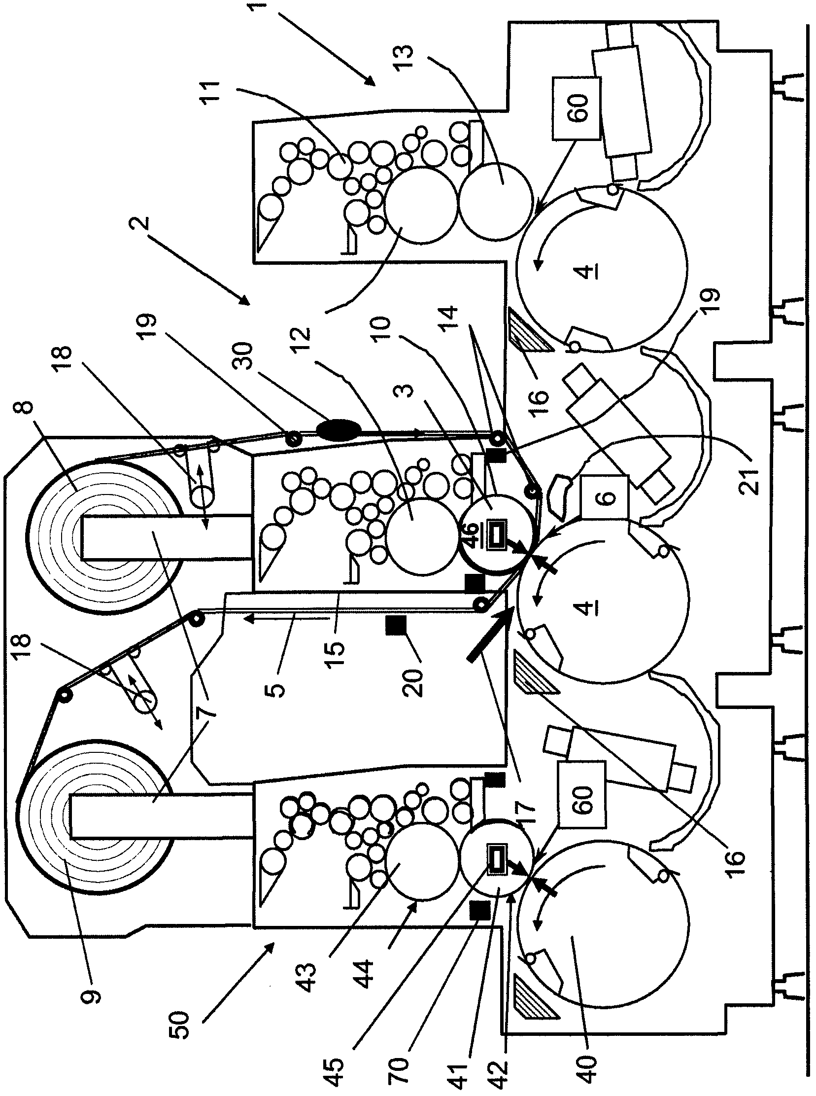
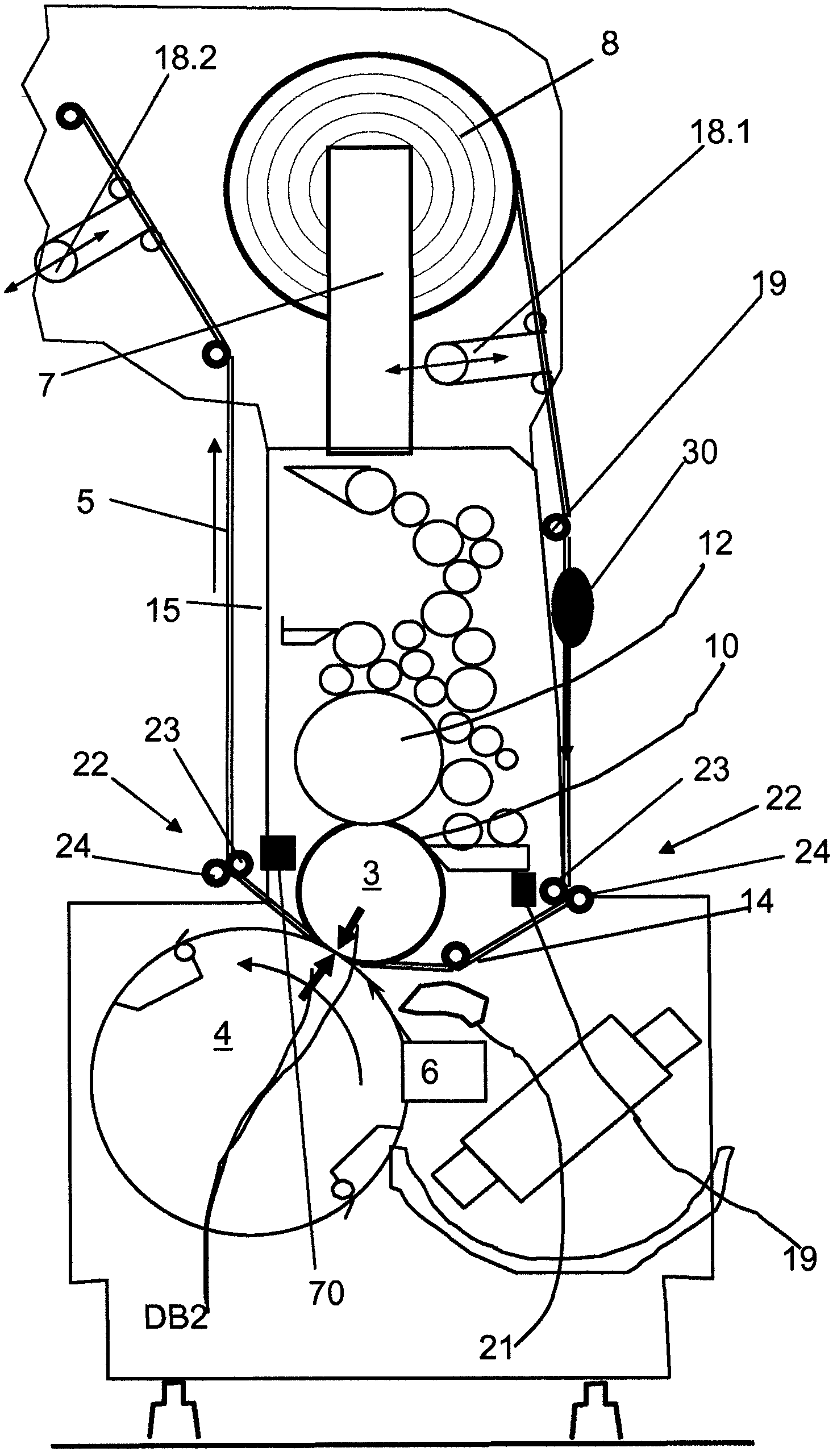
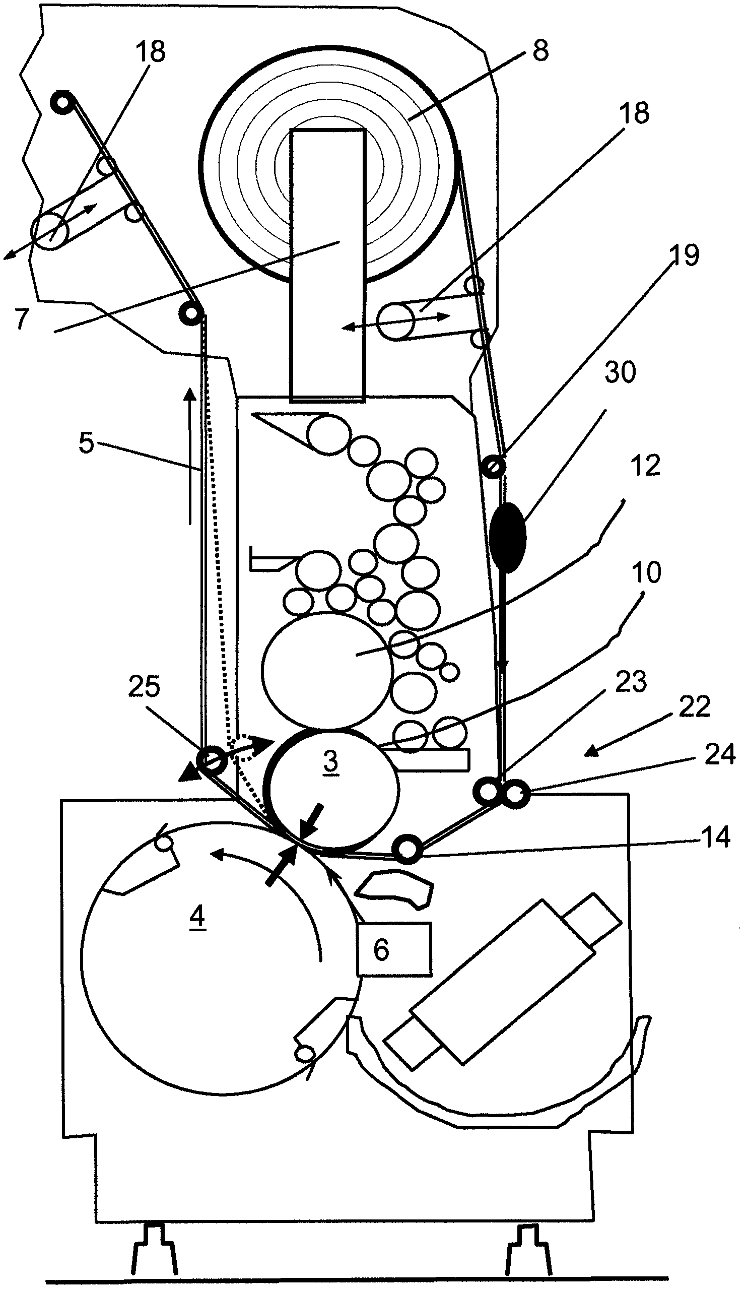
[0028] figure 1 Shown are parts of a sheet-fed rotary press (Bogenrotationsdruckmaschine), which comprises two printing units and is used for the following purposes:

[0029] - First, the printed paper is provided with a planar or image-imparting adhesive pattern (printing unit as application unit (Auftragwerk) 1 ).

[0030] - In the subsequent printing unit, the printing paper is guided under pressure together with the transfer film 5 through the transfer nip 6, (coating unit 2 ).

[0031] The application unit 1 can be a known offset printing unit with an inking unit 11 , a plate cylinder 12 and a cloth cylinder 13 . The cloth cylinder 13 cooperates with the impression cylinder 4 .

[0032] Likewise, the coating means 2 can be formed by a lithographic means. The transfer nip 6 in the coating unit 2 is formed by the pressure roller 3 and the impression cylinder 4 . The pressing roller 3 can correspond to a printing cloth cylinder. The pressure roller 3 can also correspond...


PUM


Abstract

The aim of the invention is to develop the foil guiding process in a coating unit (2) for transferring image-forming layers from a transfer foil to a medium to be printed. To achieve this, the coating unit is equipped with a restricted-area pressing plate for transferring layers from the transfer foil. This allows the targeted control of the foil feed. The transfer foil is preferably guided past a pressing roll (3) approximately tangentially to said roll and with a restricted width. Special delivery devices, which can operate cyclically, are provided for storing and delivering the foil.

Description

technical field [0001] The invention relates to a layer for rendering an image (bildgebend) from a carrier film according to the preamble of claim 1 Device transferred to printed paper (Druckbogen). Background technique [0002] It is known to produce metallic layers on printing paper by means of film transfer methods. Thus, in document EP 0 569 520 B1 a printing material and a printing device using this material are described. A machine for processing paper is shown here with a feeder (Anleger) and a delivery (Ausleger), wherein a printing unit (Druckwerk) and a coating module are arranged between these two units. The adhesive pattern (Klebstoffmuster) is applied in at least one of the printing units by means of a lithographic method. The adhesive pattern is applied (aufbringen) in a cold printing method and has a specific theme (Sujet) to give an image. In the coating module with impression cylinders and press rollers downstream of the printing unit, a film guide is a...

Claims


Application Information

Patent Timeline
IPC IPC(8): B41F19/00B41F19/06
CPCB41F19/00B41F13/08B41F16/00B41F19/062B41M1/24B41M3/006B41P2219/20B41P2219/21B41P2219/22B41P2219/51
Inventor U·皮舍尔G·雷施克J·塞尔齐希
Owner MAN ROLAND MASCHINEN AG
Why Eureka
Try Eureka