Pipelayer with cab riser
A cab, laying machine technology, applied in the direction of pipeline laying and maintenance, mechanical equipment, cranes, etc., can solve the problem of other operations on the construction site that cannot be used with pipelines
- Summary
- Abstract
- Description
- Claims
- Application Information
AI Technical Summary
Problems solved by technology
Method used
Image
Examples
Embodiment Construction
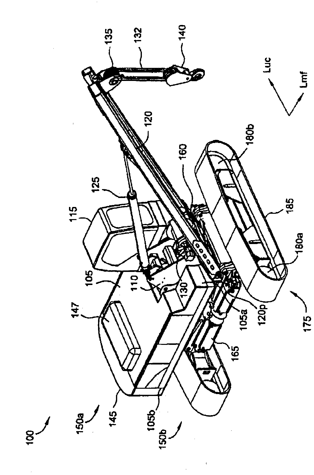
[0024] figure 2 is a perspective view of a pipe laying machine 100 according to one embodiment of the present invention. The pipelayer 100 includes a main assembly 150a mounted on an underframe 150b such that the main assembly 150a is rotatable relative to the underframe 150b. In the position shown, the longitudinal axis L of the main assembly 150a mf with the longitudinal axis L of the chassis 150b uc vertical.
[0025] Main assembly 150a may include mainframe 105, adapter 110, cab 115, boom 120, piston and cylinder assembly 125, winch 130, pulley block 135, load block 140, counterweights 145 and engine 147. The main chassis 105 has a first side 105a and a second side 105b distal to the first side 105a. The adapter 110 and the driver's cab 115 are attached to the first side 105a. The first longitudinal end of the boom 120 is pivotally connected to the adapter 110 at 120p. As used herein, the terms "articulated" or "pivot" include single-axis pivots, such as hinges, an...
PUM
 Abstract
Description
Claims
Application Information
 - R&D
- Intellectual Property
- Life Sciences
- Materials
- Tech Scout
- Unparalleled Data Quality
- Higher Quality Content
- 60% Fewer Hallucinations
Browse by: Latest US Patents, China's latest patents, Technical Efficacy Thesaurus, Application Domain, Technology Topic, Popular Technical Reports.
© 2025 PatSnap. All rights reserved.Legal|Privacy policy|Modern Slavery Act Transparency Statement|Sitemap|About US| Contact US: help@patsnap.com


