Scissor lifting device

A technology of lifting device and scissors, which is applied in the direction of lifting device, lifting frame, etc., can solve the problem of high initial pressure of the hydraulic system, achieve the effect of increasing the lifting weight and expanding the application range

Inactive Publication Date: 2011-05-11
中国人民解放军95989部队 +1
View PDF6 Cites 21 Cited by
  • Summary
  • Abstract
  • Description
  • Claims
  • Application Information

AI Technical Summary

Problems solved by technology

However, even in the presence of angles, the initial pressure of the hydraulic system is still very high

Method used


Image

  • Scissor lifting device
  • Scissor lifting device

Examples


Embodiment 1

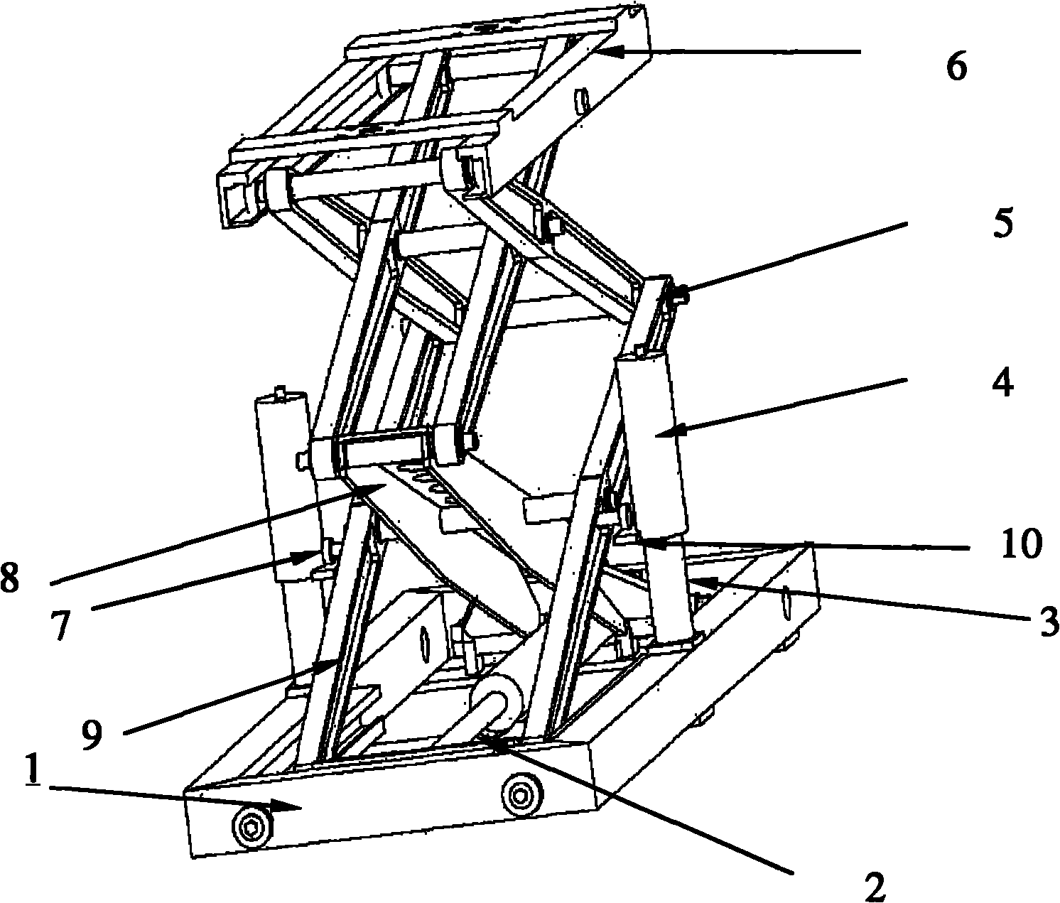
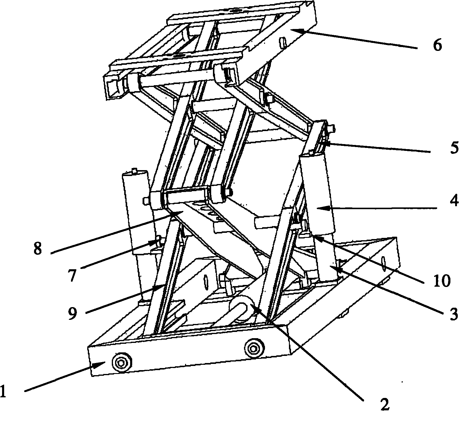
[0027] In this embodiment, the scissor lift device includes a base 1 , a scissor lift mechanism disposed on the base 1 , a hydraulic master cylinder 2 and a lifting mechanism.

[0028] Such as figure 1 As shown, the hydraulic master cylinder 2 is horizontally placed on the base 1 . The scissor lift mechanism includes two groups of lifting brackets connected in a scissor shape and a workbench 6 arranged on the top of the two groups of lifting brackets, and each group of lifting brackets consists of a plurality of lifting brackets. The rods 5 are hinged sequentially. Among the above-mentioned two groups of multiple lifting struts, the lifting struts of each layer are hinged together in pairs in a scissors-like shape. The lowermost lifting strut in one group of lifting brackets is the first lifting strut 8, and the bottom end of the first lifting strut 8 is rotatably connected to the base 1 through a rotating shaft, and the other set of lifting brackets The lowermost lifting st...

Embodiment 2

[0039] The difference between this embodiment and Embodiment 1 is that the two protruding rods are respectively fixed on both sides of the workbench 6 .

[0040] Other structures and uses in this embodiment are the same as those in Embodiment 1, and will not be repeated here.


PUM


Abstract

The invention relates to a scissor lifting device. The device comprises a base (1), a scissor lifting mechanism and a hydraulic main cylinder (2) which are arranged on the base (1), and a lifting mechanism, wherein the hydraulic main cylinder (2) is flatly lain on the base (1); the scissor lifting mechanism comprises two groups of lifting brackets in scissor connection, and a workbench frame (6) arranged on the top of the two groups of lifting brackets; each group of lifting brackets are formed by sequentially hinging a plurality of lifting brackets (5); and the lifting mechanism is used for lifting the scissor lifting mechanism upwards at the initial lifting stage. The scissor lifting device can greatly reduce the pressure of a hydraulic system, improve the maximum lifting weight and reduce the initial height of minimum lifting.

Description

technical field [0001] The invention relates to a scissor lift device. Background technique [0002] Scissor lifts are widely used in lifting equipment. As a key component of lifting equipment, scissor lifts have a direct impact on the lifting performance of the lifting platform. [0003] Some lifting equipment often require a relatively low initial height of the workbench, such as special loading and unloading lifting equipment for airports, lifting equipment for military equipment in aviation units, etc. These lifting devices often adopt a scissor lift mechanism in which the hydraulic cylinder is placed horizontally. Lift up so that the lift bars gradually rise to raise the workbench frame. [0004] When this scissor lift mechanism is at the starting point of lifting, since the included angle between the lowermost lifting strut and the ground is very small, the hydraulic system must make the lowermost lifting strut in the scissor lift mechanism Lifting the rod up to rea...

Claims


Application Information

Patent Timeline
Patent Type & Authority Applications(China)
IPC IPC(8): B66F7/08B66F7/28
Inventor 曲新生韩太平许新群杜斌张勋
Owner 中国人民解放军95989部队
Why Eureka
Try Eureka