High-pressure natural gas reducing valve

A natural gas and pressure reducing valve technology, applied in the field of pressure reducing valves, can solve the problems of shortened service life, easy damage to the gasket, unstable pressure at the outlet of the pressure reducing valve, etc. Effect

Inactive Publication Date: 2011-05-11
YISIDA ELECTROMECHANICAL EQUIP TIANJIN CITY
View PDF4 Cites 24 Cited by
  • Summary
  • Abstract
  • Description
  • Claims
  • Application Information

AI Technical Summary

Problems solved by technology

The pressure reducing valve currently used in high-pressure gaseous natural gas consists of a valve cover, a valve body connected to the valve cover, a pressure sensing diaphragm located inside the valve cover, and a pressure preset mechanism located above the pressure sensing diaphragm to pressurize it. and a spool mechanism for adjusting the opening of the valve arranged coaxially with the pressure preset mechanism. The mechanism includes an air valve connection block and a valve disc assembly composed of a valve disc rod and a valve disc ejector rod connected with the valve disc rod. The top of the valve disc rod is provided with a circumferential boss corresponding to the valve port and a sealing gasket is provided on the surface of the circumferential boss. The valve disc ejector rod passes through the valve port and is fixedly connected to the bottom of the pressure sensing diaphragm. The structure of the pressure reducing valve has the following defects: the pressure on the upper and lower surfaces of the disc assembly is affected by the pressure of the user end and the storage tank end, especially when the storage tank is working, the pressure is continuously reduced, generally reduced from 200bar to 20-30bar When the valve disc assembly of the pressure reducing valve is affected by it, it will move, and the outlet flow of the pressure reducing valve will change, making the outlet pressure of the pressure reducing valve unstable; When the pressure sensing diaphragm retracts inward due to the increase in the pressure of the low-pressure chamber, the valve disc ejector rod fixed to it drives the valve disc assembly so that the circumferential boss of the valve disc rod is always pressed against the valve port, causing the gasket on the circumferential boss to be easily damaged , shortened service life

Method used


Image

  • High-pressure natural gas reducing valve
  • High-pressure natural gas reducing valve

Examples


Embodiment Construction

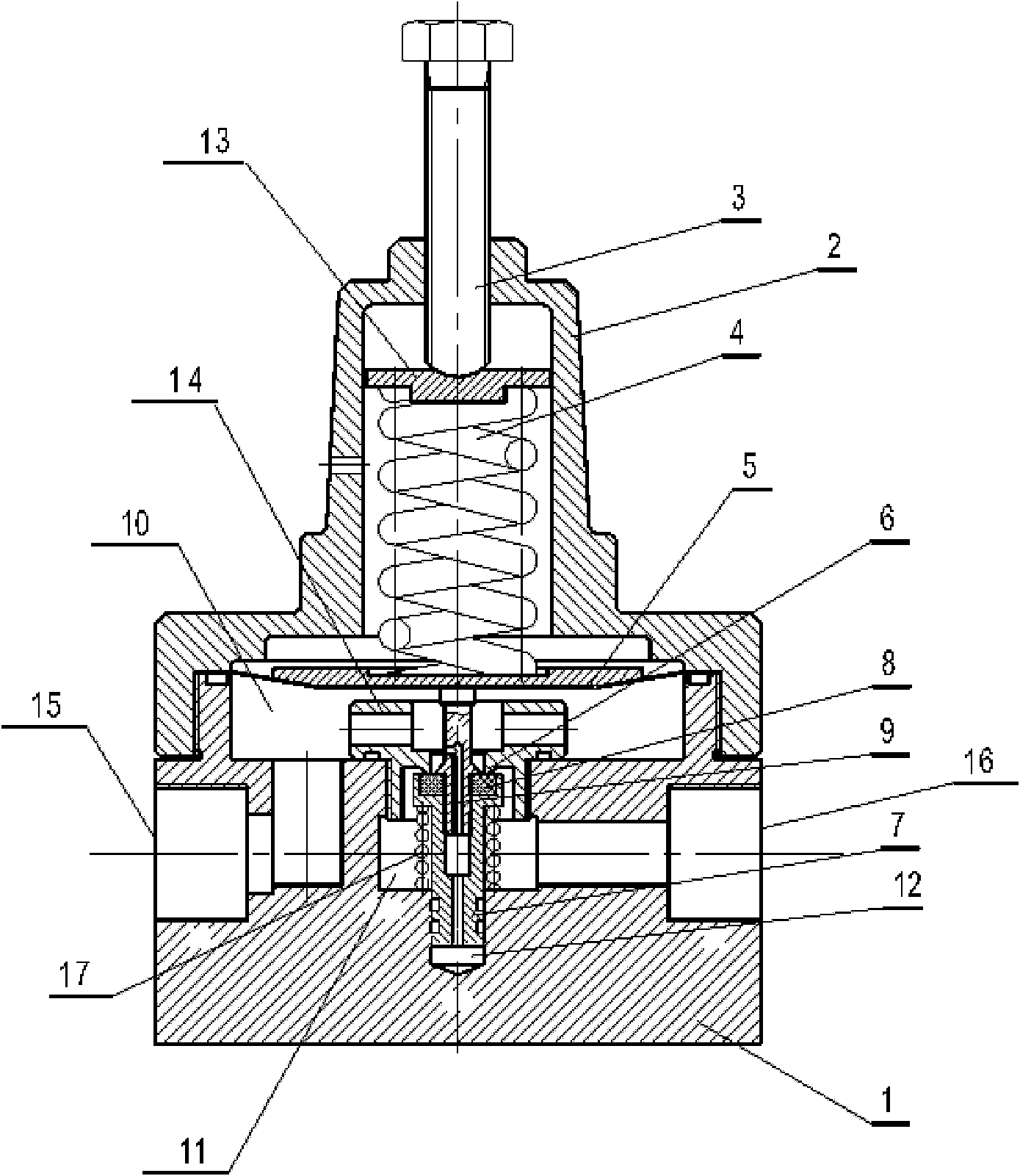
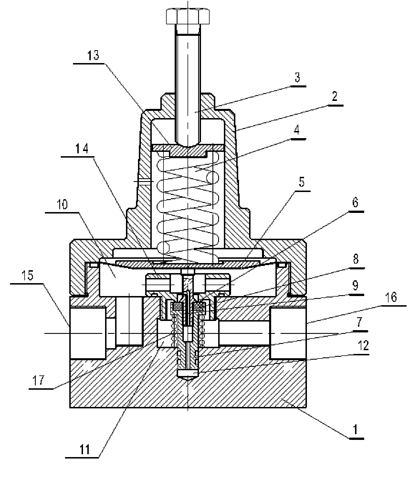
[0012] In order to enable those skilled in the art to better understand the solution of the present invention, the present invention will be further described in detail below in conjunction with the accompanying drawings and embodiments.

[0013] Such as figure 1 As shown, in the present invention, the valve cover 2, the valve body 1 connected with the valve cover, the pressure sensing diaphragm 5 inside the valve cover, the pressure preset mechanism and the The valve body 1 forms a high-pressure chamber 11 communicated with the air inlet and a low-pressure chamber 10 communicated with the air outlet through the valve body 1 through the valve core mechanism. The valve core mechanism includes an air valve connection block 14 and a valve disc assembly composed of a valve disc rod 7 and a valve disc push rod 9 connected to the valve disc rod. Connected to the center of the valve body, the top of the valve disc rod is provided with a circumferential boss corresponding to the valv...


PUM


Abstract

The invention relates to a high-pressure natural gas reducing valve which comprises a valve cover, a valve body, a pressure sensing diaphragm, a pressure preset mechanism and a valve-plug mechanism, wherein the valve-plug mechanism comprises a gas-valve connection block in which a valve port and an airflow channel are arranged and a valve clack assembly consisting of a valve-clack rod and a valve-clack ejector rod; the top of the valve-clack rod is provided with a circumferential boss, and the surface of the circumferential boss is provided with a sealing gasket; the valve-clack ejector rod passes through the valve port and is in overlap joint with the pressure sensing diaphragm; the lower part of the valve body is provided with a valve-clack groove, and a valve-clack spring is arranged between the circumferential boss of the valve-clack rod and a rabbet end face of the valve-clack groove; and a cavity is arranged in the valve clack assembly, the valve port is in the shape of cone, and the diameter of the valve port is same as that of the valve-clack rod. The high-pressure natural gas reducing valve has the advantages that because the reducing valve adopts the structure above, the axial pressure of the valve clack assembly is balanced, the pressures on the upper and lower surfaces of the valve clack assembly of the reducing valve are not affected by the pressures on a user side and a storage tank side, thereby eliminating the influence on the outlet pressure of a pressure reducing/adjusting valve when the operating pressure on the storage tank side is changed, avoiding that the valve port always produces pressures on the sealing gasket by the retraction pressure of the pressure sensing diaphragm, and prolonging the service life of the sealing gasket.

Description

technical field [0001] The invention relates to a decompression valve, in particular to a high-pressure natural gas decompression valve. Background technique [0002] Natural gas has been widely used as a clean energy source. Generally, there are three fuel supply methods: ⑴ sent to users through the urban pipeline network, ⑵ liquefied natural gas sent to users after gasification, and ⑶ high-pressure gaseous natural gas sent to user. Among the three supply methods, the construction of urban pipeline network has a long period of investment, while liquefied natural gas has just appeared in recent years, and the cost of gas source is high and expensive. Therefore, high-pressure gaseous natural gas is often used to supply gas to cities far away from natural gas sources, or to supply gas to users in cities that cannot be reached by the gas pipeline network, due to simple equipment and technology, low investment and quick results. The characteristics of this gas supply method ar...

Claims


Application Information

Patent Timeline
Patent Type & Authority Applications(China)
IPC IPC(8): F16K17/30F16K31/126
Inventor 陈兴文张建婷杨萍
Owner YISIDA ELECTROMECHANICAL EQUIP TIANJIN CITY
Why Eureka
Try Eureka