
Method for setting temperature compensation factor of pressure sensor

A pressure sensor and temperature compensation technology, applied in the direction of measuring fluid pressure, instruments, measuring devices, etc., can solve the problems of low production efficiency, incomprehension, cumbersome process, etc., and achieve the effects of improving production efficiency, simplifying operation, and being easy to implement

Active Publication Date: 2012-05-02
东莞市百赛仪器有限公司
View PDF4 Cites 1 Cited by
  • Summary
  • Abstract
  • Description
  • Claims
  • Application Information

AI Technical Summary

Problems solved by technology

[0011] The application note of MAX1452 gives a scheme to determine two temperature compensation coefficients. However, this scheme is very complicated and difficult to understand in logic, and the implementation steps are very cumbersome and time-consuming, especially when it involves different compensation temperature points. Repeated calibration operations under the environment, and the measurement switching of multiple internal parameters is required, so that this scheme has no practical guiding significance in production, or the use of this scheme to guide production efficiency is low and the process is cumbersome

Method used


Image

  • Method for setting temperature compensation factor of pressure sensor
  • Method for setting temperature compensation factor of pressure sensor
  • Method for setting temperature compensation factor of pressure sensor

Examples


Embodiment Construction

[0083] In order to further explain the principle of the method for setting the temperature compensation coefficient of the pressure sensor of the present invention, the preferred embodiment of the method for setting the temperature compensation coefficient of the pressure sensor of the present invention will now be described in detail with reference to the accompanying drawings. However, the embodiment is only for illustration and explanation. It cannot be used to limit the scope of patent protection of the present invention.

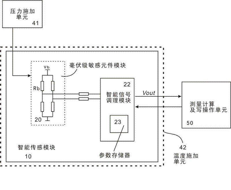
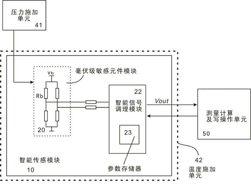
[0084] Such as figure 1 As shown, a method for setting temperature compensation coefficient of pressure sensor is implemented,

[0085] The pressure sensor includes a smart sensor module 10, the smart sensor module 10 includes a millivolt sensitive element module 20, an intelligent signal conditioning module 22, and a parameter memory 23; the output of the millivolt sensitive element module 20 is connected to smart The signal conditioning module 22, the smar...


PUM


Abstract

The invention relates to a method for setting a temperature compensation factor of a pressure sensor. An intelligent sensing module in the pressure sensor comprises a millivolt-level sensitive element module, an intelligent signal conditioning module and an internal parameter storage device in the intelligent signal conditioning module. The setting method comprises the following steps: providing a working environment for the intelligent sensing module by means of a pressure application unit and a temperature application unit; and connecting a measuring calculation and writing operation unit to the intelligent signal conditioning module for setting. In the method provided by the invention, two concise functions are used to express the relationship between the zero-point temperature drift compensation factor and the zero point as well as the relationship between the full-scale temperature drift compensation factor and the full scale, and the operating procedure is designed accordingly. By using the method, the required zero-point and full-scale temperature drift compensation factors can be calculated and written in the sensor to implement temperature compensation by simply measuringzero-point and full-scale output data at two temperature points. The method in the invention is very easy to implement in the actual production process, obviously simplifies the operation, optimizes the procedure and improves the production efficiency.

Description

technical field [0001] The invention relates to a process in the manufacturing process of a pressure sensor, in particular to a method for calculating and setting the temperature compensation coefficient of the pressure sensor. Background technique [0002] The pressure sensor is a very important device and instrument in the modern information industry. It linearly converts the pressure of the measured fluid in the industrial process into an electrical signal with a standard output such as 0.5-4.5V ratio output, 0-5V or 1-5V output. , 4-20mA output, etc. [0003] In fact, in addition to the parameter of sensing pressure, the output signal of the sensor also has many factors affected by the external environment and the resulting errors, the most common and significant of which is the change of external temperature The temperature error, referred to as temperature drift, is mainly reflected in two aspects, that is, the zero point temperature drift that affects the zero point ...

Claims


Application Information

Patent Timeline
Patent Type & Authority Patents(China)
IPC IPC(8): G01L19/04
Inventor 欧阳德利
Owner 东莞市百赛仪器有限公司
Learn More