Granularity centering measuring method utilizing CCD (charge coupled device) or CMOS (complementary metal-oxide-semiconductor) as photoelectric detector

A photodetector, particle size technology, used in measuring devices, particle size analysis, scientific instruments, etc., can solve problems such as increasing the complexity and cost of instruments

Inactive Publication Date: 2011-05-11
UNIV OF SHANGHAI FOR SCI & TECH
View PDF2 Cites 19 Cited by
  • Summary
  • Abstract
  • Description
  • Claims
  • Application Information

AI Technical Summary

Problems solved by technology

This will also increase the complexity and cost of the instrument, so there are few commercial laser particle size analyzers that use area array CCD or CMOS as photodetection devices.

Method used


Image

  • Granularity centering measuring method utilizing CCD (charge coupled device) or CMOS (complementary metal-oxide-semiconductor) as photoelectric detector
  • Granularity centering measuring method utilizing CCD (charge coupled device) or CMOS (complementary metal-oxide-semiconductor) as photoelectric detector
  • Granularity centering measuring method utilizing CCD (charge coupled device) or CMOS (complementary metal-oxide-semiconductor) as photoelectric detector

Examples


Embodiment 1

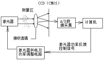
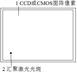
[0025] Depend on image 3 As shown, the area array CCD or CMOS is used as the multi-element photodetector, and the laser uses an adjustable power laser. The laser power supply and power adjustment circuit are connected to the laser. Output signal, control the laser power supply and power adjustment circuit to adjust the laser power according to the signal of CCD or CMOS, when the maximum output signal of all pixels of CCD or CMOS reaches slightly lower than saturation, such as reaching 95% of the saturation signal, stop adjusting the laser The computer records the output signal of CCD or CMOS, and according to the size of the output signal of each pixel of the recorded CCD or CMOS, determine the pixel point with the largest output signal as the position of the converging laser point, and use this as the spatial distribution of particle scattering light energy The central point is used as the basis for the following theoretical calculations, such as Figure 4 shown. Then add...

Embodiment 2

[0033] Depend on Figure 5 As shown, the difference from Embodiment 1 is that the laser power is not automatically adjusted by the computer according to the signal size measured by the CCD or CMOS, but the operator manually adjusts the laser power to the most appropriate size. Adjusting the laser power manually can simplify the structure of the instrument, especially suitable for occasions requiring low-cost instruments.


PUM


Abstract

The invention discloses a granularity centering measuring method utilizing a CCD (charge coupled device) or CMOS (complementary metal-oxide-semiconductor) as a photoelectric detector. The method comprises the following steps: 1, adopting a CCD or CMOS as a multielement photoelectric detector, utilizing a power adjustable laser, and lowering the power of the laser before granularity of granules ismeasured, thus a low power laser beam is not saturated when being focused on the CCD or CMOS; and recording the pixel position of the laser spot on the CCD or CMOS, and taking the measured pixel of the spot as a scattering center position during granularity measurement; 2, adjusting the power of the laser to the limit power at which the pixel with a peak signal is not saturated, carrying out measurement, and recording the distribution of lights scattered by the granules; and 3, calculating according to the light scattering theory to obtain granularity distribution of the granules on the basisof the initially determined scattering center position. According to the invention, the defects that the traditional laser granularity instrument is complex in centering and the pixel is easily saturated or damaged when the CCD or CMOS is adopted as the photoelectric detector are solved, a hardware centering device is omitted, no concentric adjusting is required, and the granularity measurement of the granules can be realized.

Description

technical field [0001] The invention relates to a particle size measurement method of a laser particle size analyzer, in particular to a centering measurement method of a laser particle size analyzer. Background technique [0002] The laser particle size analyzer has been widely used in many fields. Its basic principle is that when a laser beam is incident on the particle sample to be measured, due to the scattering effect, the incident light will deviate from the original incident direction and scatter in all directions. The spatial distribution of light scattering is related to the size of the particles. When the particles are small, the forward scattered light is relatively weak, and when the particles are large, the forward scattered light is relatively strong. The laser particle size analyzer uses this principle to measure the distribution of scattered light in different directions, and then obtains the particle size distribution of the measured particles according...

Claims


Application Information

Patent Timeline
Patent Type & Authority Applications(China)
IPC IPC(8): G01N15/02
Inventor 蔡小舒苏明旭
Owner UNIV OF SHANGHAI FOR SCI & TECH
Why Eureka
Try Eureka