
Dipolar permanent magnet synchronous submersible electric motor

A permanent magnet synchronous motor technology, applied in the direction of synchronous machine parts, electric components, magnetic circuit rotating parts, etc., can solve problems such as lack of asynchronous starting, underutilization of permanent magnets, difficulties in electromagnetic scheme design, etc. , to achieve the effect of strong magnetic field energy

Active Publication Date: 2015-08-26
山东颜山泵业有限公司
View PDF7 Cites 0 Cited by
  • Summary
  • Abstract
  • Description
  • Claims
  • Application Information

AI Technical Summary

Problems solved by technology

Due to the existence of the rotor permanent magnet, the average torque-slip curve has a lower concave point at low speed. Starting to limit the starting current), the higher starting current needs to be suppressed by the optimized design of the rotor slot shape. On the other hand, in order to increase the minimum torque and reduce the amount of permanent magnets, it is necessary to increase the number of stator winding turns, which makes the manufacturing cost and At the same time, due to the existence of the starting squirrel cage winding, the space for placing the permanent magnet is limited. On the one hand, if the cross-sectional hole of the starting squirrel cage rotor guide bar is too large, the permanent magnet will be closer to the rotating shaft, and the permanent magnet will not be obtained. To make full use of it, it is necessary to add more permanent magnet thickness to ensure the electromagnetic performance; on the other hand, if the cross-section of the squirrel cage rotor bar hole is too small, the current in the rotor bar will be too large, which may make the rotor bar If the heat generation is too large, it will not be able to play the role of asynchronous starting
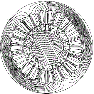
[0005] At the same time, due to the influence of the small diameter of the well, all submersible pumps for wells are bipolar pumps, so the design of the submersible motor for supporting wells must also be a bipolar motor, but the magnet embedded in the rotor is made of bipolar magnets. The scheme design is more difficult, the magnetic field lines of the stator yoke are relatively dense, so the stator yoke is relatively easy to saturate, so we need a thicker yoke
However, in the case of a certain size of the motor, if the yoke is thicker, there will be less space for placing copper wires; we know that if there is less copper placed, it will bring many problems, such as wire load, stator copper loss, hair loss, etc. heat, efficiency, etc.

Method used


Image

  • Dipolar permanent magnet synchronous submersible electric motor
  • Dipolar permanent magnet synchronous submersible electric motor
  • Dipolar permanent magnet synchronous submersible electric motor

Examples


Embodiment Construction

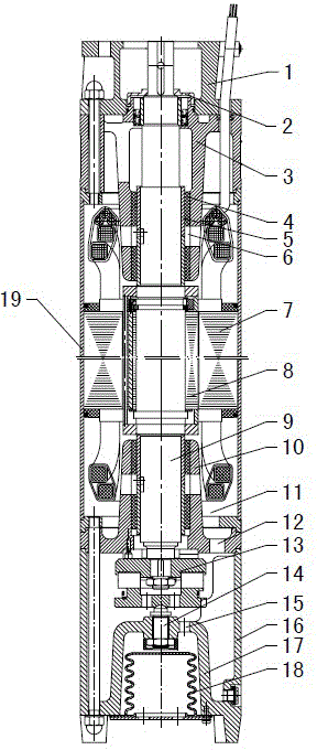
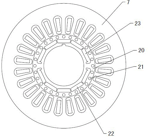
[0032] Figure 1~3 It is the best embodiment of the two-pole permanent magnet synchronous submersible motor, below in conjunction with the attached Figure 1~3 The present invention will be further described.

[0033] refer to Figure 1~3 , the two-pole permanent magnet synchronous submersible motor includes a stator 7 and a rotor 8 fixed in the casing 19, a motor shaft 9 is coaxially fixed inside the rotor 8, and the rotor 8 is a two-pole rotor composed of a plurality of magnetic steels, and the pole arc coefficient is 0.87, the rotor 8 includes a plurality of axially stacked rotor punches 20, and the outer circumference of the rotor punches 20 is uniformly provided with a plurality of starting rod fixing holes 21, and a plurality of starting rods are respectively fixed in the starting rod fixing holes 21 to form a starting In the squirrel cage, a plurality of N-pole magnetic steel fixing grooves 22 and a plurality of S-pole magnetic steel fixing grooves 23 are arranged on ...


PUM


Abstract

The invention provides a dipolar permanent magnet synchronous submersible electric motor, and belongs to the technical field of submersible motors. The dipolar permanent magnet synchronous submersible electric motor adopts the structure that a rotor (8) is a dipolar rotor consisting of a plurality of magnetic steel, and the pole arc coefficient is 0.85-0.89; the rotor (8) comprises a plurality of axially stacked rotor punching plates (20); a plurality of start lever fixing holes (21) are uniformly formed in the outer circumference of the rotor punching plates (20); a plurality of N-pole magnetic steel fixing grooves (22) and a plurality of S-pole magnetic steel fixing grooves (23) are formed in the rotor punching plates (20) on the radial inner sides of the start lever fixing holes (21); the magnetic steel is embedded and fixed in the N-pole magnetic steel fixing grooves (22) and the S-pole magnetic steel fixing grooves (23). Through the structure of the rotor (8) with the larger polar arc coefficient, that is, permanent magnets can be spread as much as possible, so that the stronger magnetic field energy can be provided to solve the problems that yoke magnetic lines of a stator (7) of the dipolar rotor is relatively intensive, the yoke of the stator (7) is likely to be saturated, and the paths of the magnetic lines are relatively long.

Description

technical field [0001] A two-pole permanent magnet synchronous submersible motor belongs to the technical field of submersible motors. Background technique [0002] The permanent magnet synchronous motor does not need the stator to provide additional excitation current because its excitation structure is realized by permanent magnets. Therefore, the power factor of the motor can be made quite high (theoretically it can reach 1). Due to the extremely low reactive component of the stator current, the stator current is significantly lower than that of the asynchronous motor with the same number of poles and the same capacity, especially in the case of a motor with a high number of poles, which can be reduced by 25%-40%, so that the copper consumption of the stator can be reduced 30%-50%. Since the rotor has no current passing through it, unlike the asynchronous motor, the rotor has current, resulting in loss. This part of the loss generally accounts for 5-10% of the total los...

Claims


Application Information

Patent Timeline
Patent Type & Authority Applications(China)
IPC IPC(8): H02K21/02H02K1/27H02K5/20H02K5/128
Inventor 侯萍陈玲杜皇生
Owner 山东颜山泵业有限公司
Learn More