Fixed beam antenna array, base station and method for transmitting signals via a fixed beam antenna array

A technology of fixed beams and antenna arrays, applied to antennas, antenna parts, antenna supports/mounting devices, etc., can solve problems such as ineffective use, and achieve the effects of simplified structure, low junction temperature, and high antenna gain

Inactive Publication Date: 2003-11-05
NOKIA CORP
View PDF0 Cites 6 Cited by
  • Summary
  • Abstract
  • Description
  • Claims
  • Application Information

AI Technical Summary

Problems solved by technology

Therefore, this method cannot be effecti

Method used


Image

  • Fixed beam antenna array, base station and method for transmitting signals via a fixed beam antenna array
  • Fixed beam antenna array, base station and method for transmitting signals via a fixed beam antenna array
  • Fixed beam antenna array, base station and method for transmitting signals via a fixed beam antenna array

Examples


Embodiment Construction

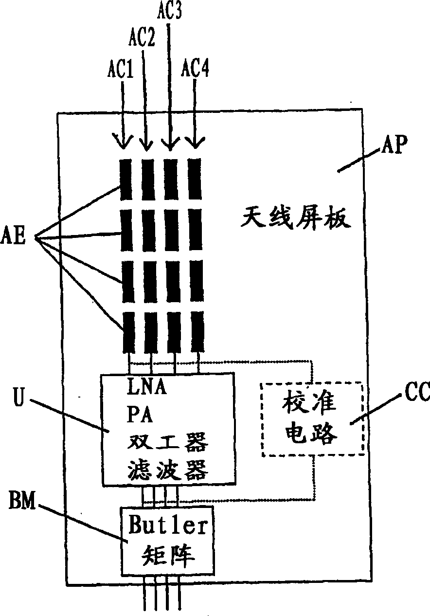
[0037] figure 1 A four-beam antenna array of a macro-site base station is shown, with a two-dimensional matrix of antenna elements AE.
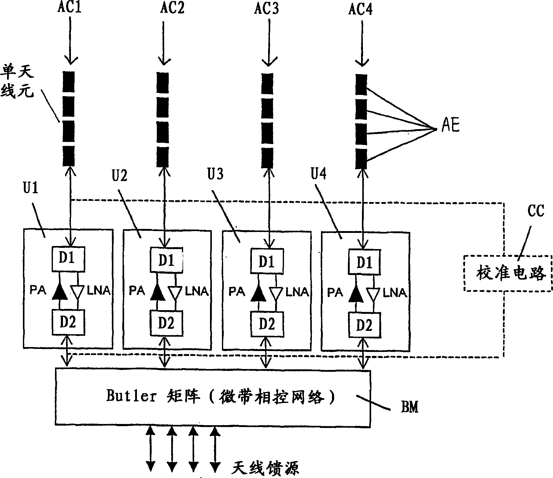
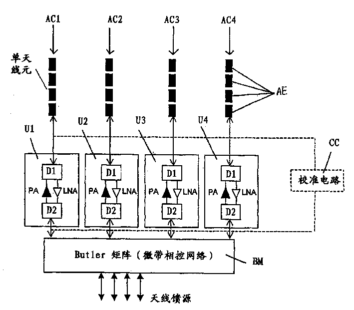
[0038] This matrix is ​​formed by columns AC1-AC4 of four antenna elements AE arranged on an antenna panel AP. Each of the four columns AC1-AC4 includes four antenna elements AE. Columns AC1-AC4 are connected to a unit U having some low noise amplifiers, active linear power amplifiers, duplexers and filters. A calibration circuit CC is accessible to those inputs and outputs of unit U. Unit U is also connected to a Butler matrix BM.

[0039] A unit U including a low noise amplifier, a power amplifier, a duplexer and a filter is integrated on the antenna panel AP. Likewise, the calibration unit CU and the Butler matrix BM are also integrated on the antenna panel AP.

[0040] figure 1 The antenna array shown functions as follows.

[0041] The transceiver unit (not shown) of the base station generates the signals to be transmitted and proc...


PUM


Abstract

The present invention proposes a fixed beam antenna array and a base station including the antenna array. In order to provide a simpler and more efficient fixed-beam antenna array, the proposed antenna array includes columns (AC1-AC4) of antenna elements (AE) emitting the generated signals, this fixed-beam antenna array also includes Beamforming means for adjusting the phase angle and/or amplitude of the generated signals and a number of columns (AC1-AC4) respectively assigned to said antenna elements (AE), arranged between said beamforming means (BM) and said columns Active power amplifiers (PA) between (AC1-AC4) for amplifying the signal output by said beamforming means and for delivering the amplified signal to the antenna elements (AE) assigned to transmit the signal. The invention also proposes a method of transmitting the generated signal through such a fixed beam antenna array.

Description

technical field [0001] The invention relates to a fixed beam antenna array with beam selection and a base station of a mobile communication network, especially a cellular mobile communication network. The invention also relates to a method of transmitting signals through a fixed-beam antenna array. Background technique [0002] In the base station site solution, some efforts have been made to improve the antenna efficiency, because the improved antenna efficiency allows the use of fewer base station sites or smaller antenna panels. In addition, the total power of the base station can also be kept small. Another reason to increase antenna efficiency is that downlink capacity may be a limiting factor in the future, especially as Internet-type data becomes more prevalent. This relates in particular to CDMA (Code Division Multiple Access) systems. [0003] There are two different approaches used to increase the downlink capacity of a base station using an antenna array to pro...

Claims


Application Information

Patent Timeline
IPC IPC(8): H01Q1/24H01Q3/26H01Q3/40H01Q23/00
CPCH01Q1/246H01Q3/267H01Q3/40H01Q23/00
Inventor 朱哈·伊利塔罗
Owner NOKIA CORP
Why Eureka
Try Eureka