Optical sheet and manufacturing method therefor

a technology of optical sheets and manufacturing methods, applied in the field of optical sheets, to achieve the effects of reducing light loss, reducing design difficulty, and reducing material costs

Inactive Publication Date: 2010-04-29
SUREGIANT TECH
View PDF7 Cites 6 Cited by
  • Summary
  • Abstract
  • Description
  • Claims
  • Application Information

AI Technical Summary

Benefits of technology

[0011]The invention aims to provide an optical sheet which has lower material cost, reduce light loss, and decrease the difficulty in design.

Problems solved by technology

Second, a pressing plate is covered on the uncured photo resin.

Method used


Image

  • Optical sheet and manufacturing method therefor
  • Optical sheet and manufacturing method therefor
  • Optical sheet and manufacturing method therefor

Examples


Embodiment Construction

[0027]Reference will now be made in detail to the preferred embodiments of the present invention, examples of which are illustrated in the accompanying drawings. Wherever possible, the same reference numbers are used in the drawings and the description to refer to the same or like parts.

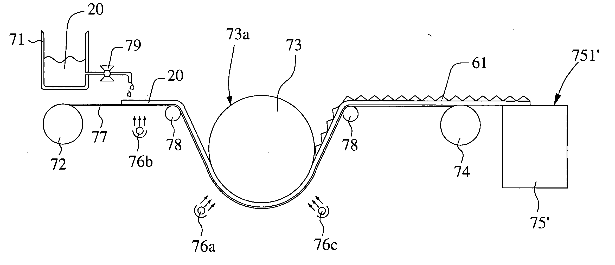
[0028]Please refer to FIG. 2A to FIG. 2E, the manufacturing process of optical sheet of the embodiment in this invention is shown. First, please refer to FIG. 2A, a forming module 30 which has pluralities of second microstructures 32 is provided. The second microstructures 32 are prism-shape troughs. The forming module 30 is made of metal, for instance: nickel. Furthermore, the surface 31 of the forming module 30 is coated with Teflon.

[0029]Then please refer to FIG. 2B, a liquid photo resin 20 with viscosity above 50 cps is coated on the surface 31 of the forming module 30. The photo resin can be cured when irradiated by light within certain wavelength band regions. In this embodiment, the photo resi...


PUM

PropertyMeasurementUnit
thicknessaaaaaaaaaa
thicknessaaaaaaaaaa
thicknessaaaaaaaaaa

Abstract

The present invention provides an optical sheet placed in a backlight assembly and the manufacturing method therefor. There are pluralities of first microstructures on the surface of the optical sheet. The optical sheet is mainly made of cured photo resin, for instance: ultraviolet glue. The optical sheet has higher performance and lower cost.

Description

BACKGROUND OF THE INVENTION[0001]1. Field of the Invention[0002]The invention is an optical sheet, especially an optical sheet in a backlight assembly.[0003]2. Description of the Prior Art[0004]A liquid crystal display emits lower radiation than a cathode ray tube display, and the manufacturing cost of the liquid crystal display has been reduced obviously recently. This is why the cathode ray tube display has been gradually replaced by a liquid crystal display. In general, the liquid crystal display includes a backlight assembly and a LCD panel. The backlight assembly is responsible for providing light to the LCD panel.[0005]Please refer to FIG. 1A, a conventional backlight assembly is shown. The backlight assembly 100 includes pluralities of cold cathode fluorescent lamps 110, a reflector 120, a diffusion plate 130, a diffusion film 142, and a brightness enhancement film 144. The cold cathode fluorescent lamps 110, arranged at a plurality of intervals, are used to provide light. Th...

Claims


Application Information

Patent Timeline
Patent Type & Authority Applications(United States)
IPC IPC(8): B32B3/00G02B1/12B29D11/00
CPCB29D11/00663G02B5/0242Y10T428/24479G02B5/045G02B5/0278G02B5/04G02F1/1335
Inventor SUNG, CHANG-CHIHLEE, CHEN-SHENGYANG, YUN-PIN
Owner SUREGIANT TECH
Why Eureka
Try Eureka