
Corner clock

A technology of wall corners and corner clocks, which is applied in the field of decorative clocks, can solve the problems of unsightly decoration effects and other problems, and achieve the effect of avoiding eye discomfort

Inactive Publication Date: 2011-05-11
邵跃明 +1
View PDF6 Cites 0 Cited by
  • Summary
  • Abstract
  • Description
  • Claims
  • Application Information

AI Technical Summary

Problems solved by technology

[0002] Clocks are indispensable daily timekeeping supplies for people, but the pendulum clocks currently on the market cannot play a very good decorative effect on the space, especially in the corners of the space, the decorative effect of the pendulum clock is extremely unsightly

Method used


Image

  • Corner clock
  • Corner clock
  • Corner clock

Examples


Embodiment Construction

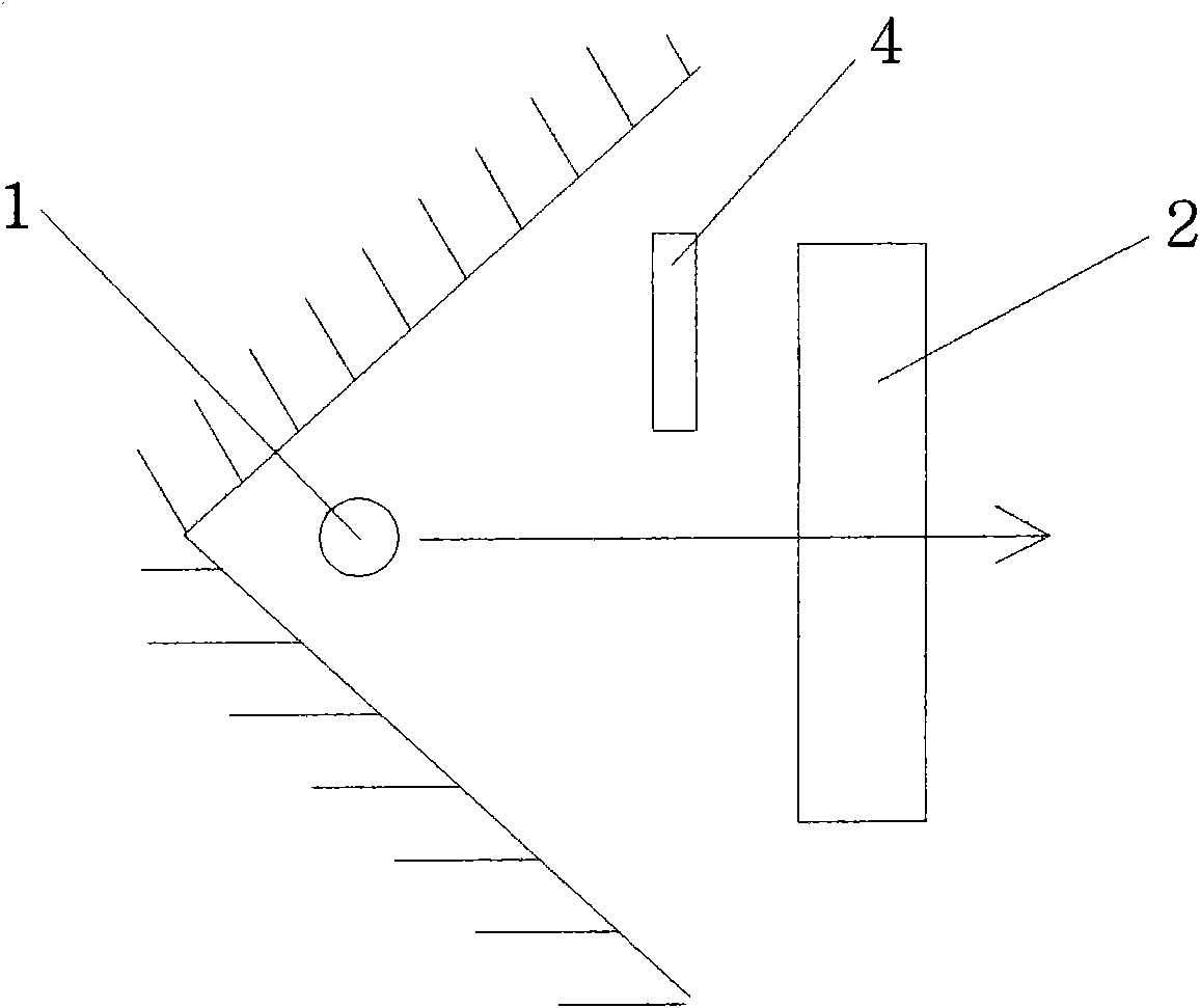
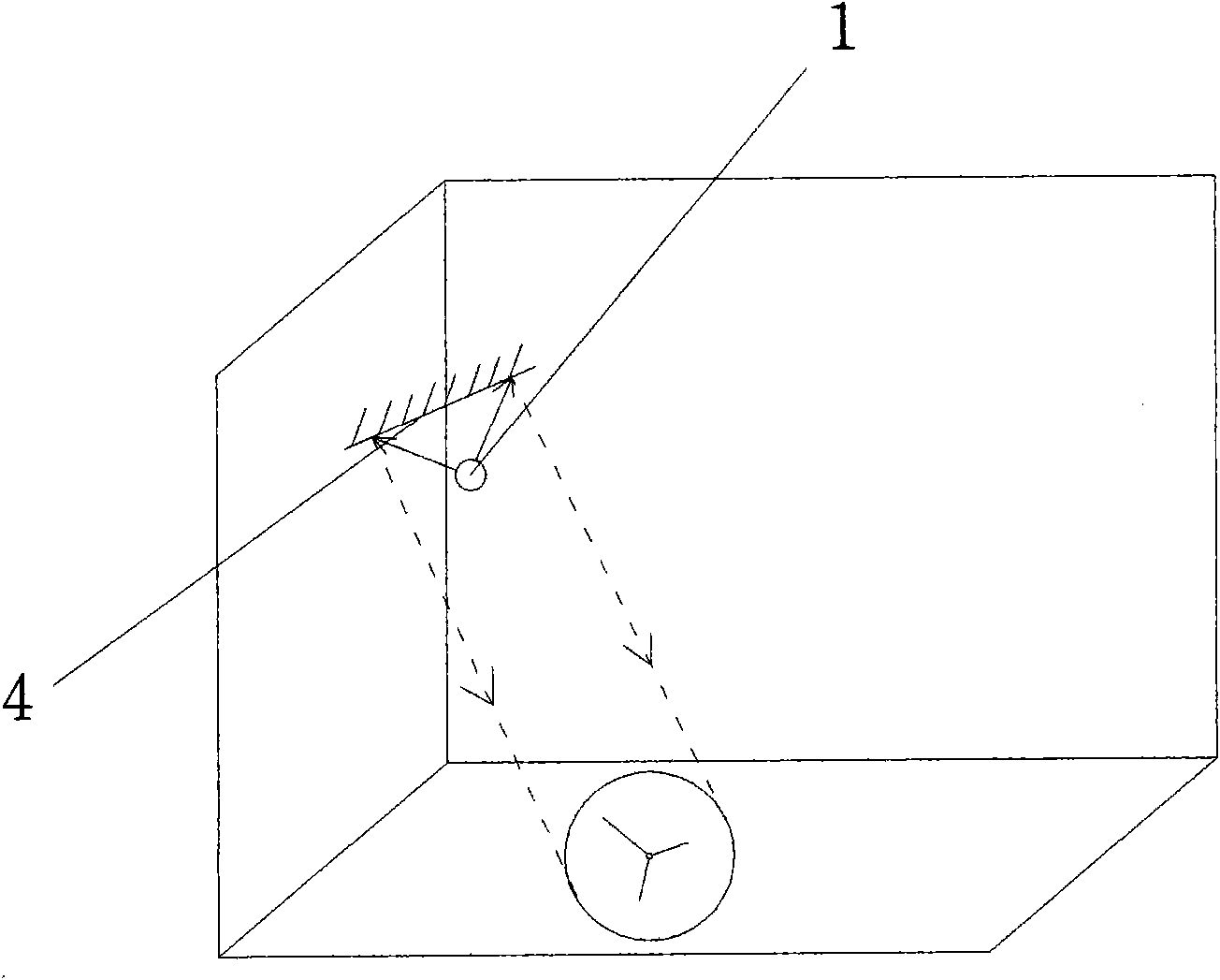
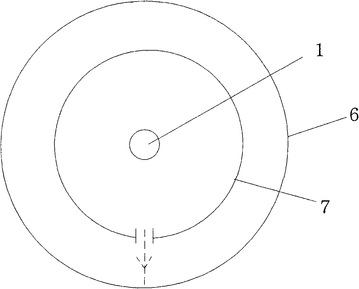
[0027] Such as figure 1 , figure 2 and Figure 4 The shown corner clock is installed in the space surrounded by two planes. The top of the corner clock is provided with a shelf for people to place storage items. It also includes a night light device 1, and the night light device emits The light energy passes through the clock panel 2, and the installation angle of the night light device 1 is adjustable.

[0028] The housing of the corner clock is provided with four light-transmitting areas 3 , so that the light emitted by the night light device 1 can pass through the light-transmitting areas 2 to achieve night light lighting effect.

[0029] The corner clock is provided with a reflector 4 in its installation space, so that the light energy emitted by the night light device 1 is reflected by the reflector 4 to achieve the lighting effect of the night light. The installation angle of the reflector 4 is adjustable, thus The light emitted by the night light device 2 can be set...


PUM


Abstract

The invention discloses a corner clock, which is arranged in a space surrounded by two or more planes, a space surrounded by one or more curved surfaces or a space surrounded by mixing the planes and the curved surfaces. The corner clock breaks through the conventional placing way of a pendulum clock, so the pendulum clock is more decorative, means much in little, is graceful and fashionable, and reflects the taste and the style of a house owner.

Description

technical field [0001] The invention relates to a decorative clock, especially a timing device for decorating a corner position of a space where it is placed. Background technique [0002] Clock is an indispensable daily timing article for people, but the pendulum clocks on the market cannot play a good decorative effect on the space, especially in the corner position of the space, the decorative effect of the pendulum clock is extremely unsightly. Contents of the invention [0003] In order to overcome the above-mentioned drawbacks, the object of the present invention is to provide a timekeeping device that decorates the corner of the space where it is placed. [0004] To achieve the above object, the technical solution of the present invention is: [0005] A corner clock is characterized in that it is installed in a space surrounded by two or more planes or in a space surrounded by one or more curved surfaces or in a space surrounded by a mixture of planes and curved su...

Claims


Application Information

Patent Timeline
IPC IPC(8): G04B45/00G04B47/00F21V7/00G04B19/30
Inventor 邵跃明欧俊兵
Owner 邵跃明
Learn More