Transferring system for magnetic levitation

A technology of transmission system and magnetic force, applied in the direction of magnetic attraction or thrust holding device, electrical components, etc., can solve problems such as damaged components, noise, and generation of particles

Inactive Publication Date: 2011-05-11
SFA ENG CORP
View PDF12 Cites 10 Cited by
  • Summary
  • Abstract
  • Description
  • Claims
  • Application Information

AI Technical Summary

Problems solved by technology

[0015] The present invention provides a magnetic levitation transmission system, which uses the magnetic levitation method as one of the non-contact methods when transporting various objects (including transmission boxes), especially large-sized objects, so as to solve the problem of damage due to friction and wear Problems with components and problems causing noise and solving the problem of particle generation, and also easy and correct control of the suspension unit
[0016] Another aspect of the present invention provides a magnetic levitation conveying system, which adopts the magnetic levitation method as one of the non-contact methods when conveying various objects (including conveying boxes), especially large-sized objects, thereby solving problems caused by friction. And the problem of wearing and damaging components and the problem of causing noise and solving the problem of generating particles, and also effectively dampens the shock transmitted to the loading unit through the conveying body loaded with objects and conveyed along the track
[0017] Yet another aspect of the present invention provides a magnetic levitation conveying system, which adopts the magnetic levitation method as one of the non-contact methods when conveying various objects (including conveying boxes), especially large-sized objects, thereby solving problems caused by friction and the problem of damaging components due to wear and tear, the problem of causing noise, and the problem of generating particles, and also guides the transfer body to land stably on the track

Method used


Image

  • Transferring system for magnetic levitation
  • Transferring system for magnetic levitation
  • Transferring system for magnetic levitation

Examples


Embodiment Construction

[0059] In order to fully understand the present invention and its advantages, reference will now be made to the accompanying drawings, which illustrate embodiments of the invention.

[0060] Hereinafter, the present invention will be described in detail by explaining embodiments of the invention with reference to the accompanying drawings. The same reference numbers in the various drawings represent the same elements.

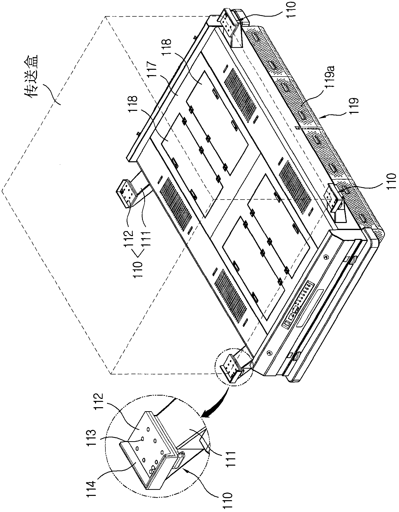
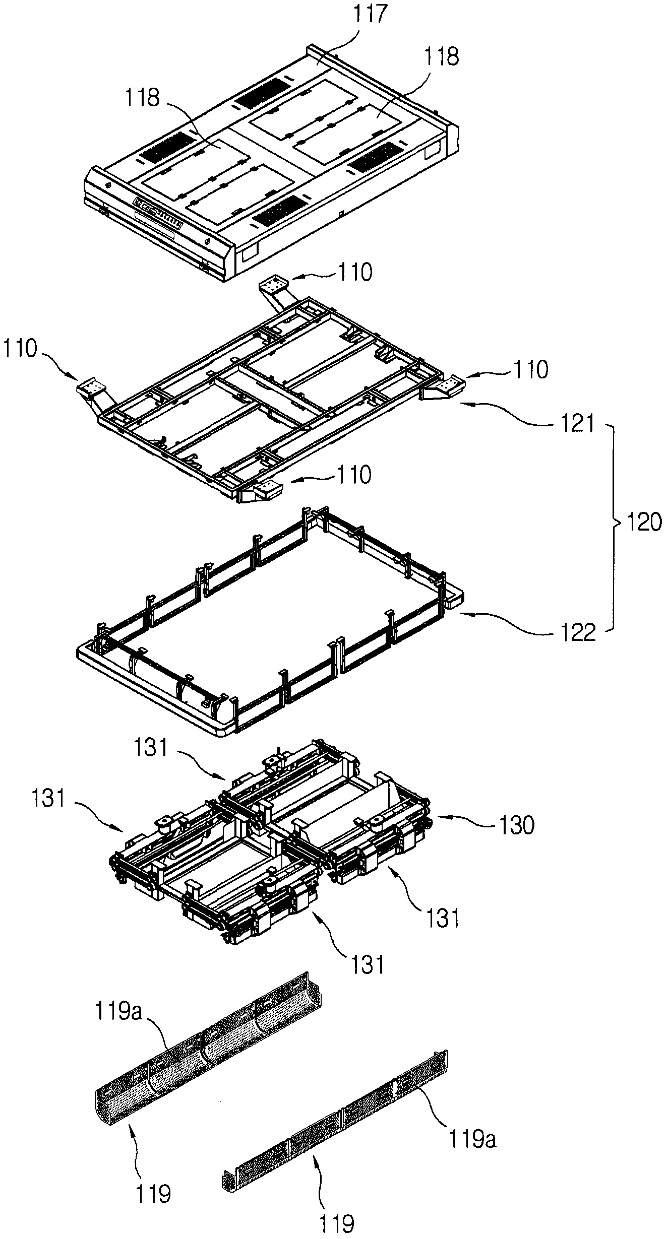
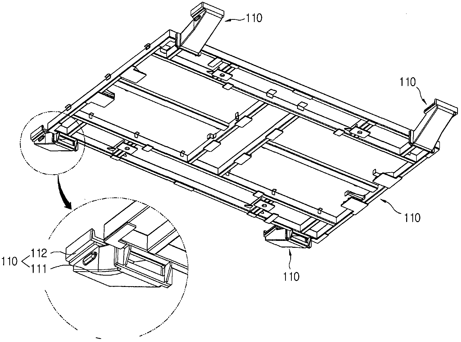
[0061] figure 1 is a perspective view of a magnetic levitation transport system according to an exemplary embodiment of the present invention; figure 2 for figure 1 Partial exploded perspective view of ; image 3 for figure 1 An enlarged view of the shared support frame in ; Figure 4 is an enlarged perspective view of the suspension unit; Figure 5 to Figure 8 for Figure 4 plan, back view, left side view and front view of ; Figure 9 for Figure 4 An enlarged perspective view of a sub-levitation / propulsion unit in the levitation unit shown; Figure...


PUM


Abstract

The invention discloses a transferring system for magnetic levitation, which comprises a common support frame, a track, a suspension unit, a propulsion unit and a power supply unit.A loading unit for loading objects is coupled to the common support frame.The track is equipped with a route for transmitting the common support frame.The suspension unit comprises a plurality of sub suspension units apart from each other and connected with the common support frame, wherein the common support frame suspends to a preset height with respect to the track.The propulsion unit connected with the common support frame is used for providing propulsive force, so that the suspended common support frame is transmitted along the route of the track.The power supply unit supplies power for the suspension unit and the propulsion unit.By adopting the above configuration, when various objects (including transmission boxes), especially large-sized objects are transmitted, magnetic levitation method is adopted as one of non-contact methods, thereby avoiding the damage of components due to friction and abrasion, the noise problem and the generation of particles.Meanwhile, the suspension unit can be easily and correctly controlled.

Description

[0001] Related Application Cross Reference [0002] This application claims priority to the following Korean patent applications filed at the Korean Intellectual Property Office: No. 10-2009-0102729 filed on October 28, 2009, No. 10-2009-0102729 filed on October 28, 2010 The disclosures of Korean Patent Applications No. 10-2009-0102730 and No. 10-2009-0102731 filed on October 28, 2009 are incorporated herein by reference in their entirety. technical field [0003] The present invention relates to a magnetic levitation transmission system, and more specifically, to a magnetic levitation transmission system that adopts a magnetic levitation method as a means of transporting various objects (including transmission boxes), especially large-sized objects. A non-contact type method to solve the problem of damage to components due to friction and wear and the problem of causing noise and the problem of particle generation, and can easily and correctly control the suspension unit. B...

Claims


Application Information

Patent Timeline
Patent Type & Authority Applications(China)
IPC IPC(8): H02N15/00
Inventor 李京南朴浚完张宰植
Owner SFA ENG CORP
Why Eureka
Try Eureka