Method for measuring laser linewidth of ultra-narrow linewidth laser

A technology of ultra-narrow line width and laser line width, which is applied in the field of laser line width measurement of lasers, can solve the problems of submerged laser line width and difficult measurement of laser line width

Active Publication Date: 2016-05-11
CHONGQING UNIV
View PDF5 Cites 9 Cited by
  • Summary
  • Abstract
  • Description
  • Claims
  • Application Information

AI Technical Summary

Problems solved by technology

[0004] With the development of ultra-narrow linewidth laser technology, the laser linewidth is becoming narrower and narrower. For ultra-narrow linewidth lasers with a linewidth below 100 Hz, the aforementioned first and second methods are completely inapplicable. If the above-mentioned third and fourth methods are used to measure the laser linewidth value of this ultra-narrow linewidth laser, it is necessary to use a single-mode fiber with a length of several hundred kilometers as the delay fiber. The Gaussian linewidth formed by the generated 1 / f noise can reach the level of several kHz, and the noise will drown out the laser linewidth to be measured. Although Voigt fitting can be used to separate the Lorentz linetype from the Gaussian linetype, However, the Voigt fitting has been approximated, and the Gaussian linewidth formed by the noise is an order of magnitude higher than the Lorentz linewidth of the laser itself, so it is difficult to accurately measure the laser linewidth by using the Voigt fitting

Method used


Image

  • Method for measuring laser linewidth of ultra-narrow linewidth laser
  • Method for measuring laser linewidth of ultra-narrow linewidth laser
  • Method for measuring laser linewidth of ultra-narrow linewidth laser

Examples


Embodiment Construction

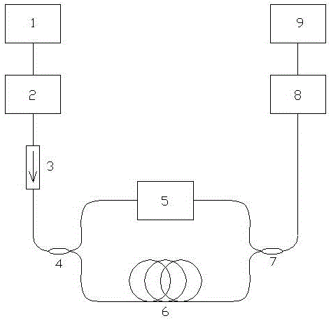
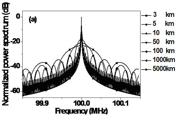
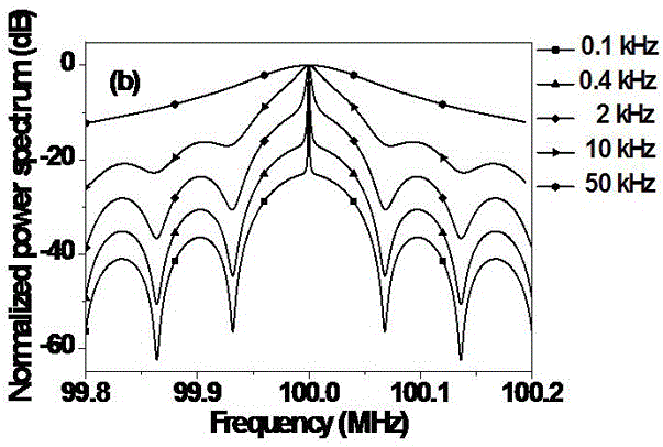
[0046] A method for measuring the laser linewidth of an ultra-narrow linewidth laser, the innovation of which is: using a self-heterodyne detection system to obtain the power spectrum of an ultra-narrow linewidth laser under heterodyne conditions; , select a peak and a trough that are adjacent to each other, calculate the difference ΔS of the contrast between the peak and the trough on the power spectrum, and then calculate the laser linewidth Δf according to the following formula:

[0047] ΔS=10log 10 S(F1,Δf)-10log 10 S(F2,Δf)

[0048] Wherein, F1 is the detection frequency of the spectrum analyzer at the peak position on the power spectrum, and F2 is the detection frequency of the spectrum analyzer at the valley position on the power spectrum;

[0049] In the previous formula, S(F1,Δf)=S1 # ·S2 # , S(F2,Δf)=S1 * ·S2 * ; where, S1 # is the Lorentzian line spectrum corresponding to F1, S2 # is the periodic sine modulation spectrum corresponding to F1, S1 * is the Lor...


PUM


Abstract

The invention discloses a method for measuring laser linewidth of an ultra-narrow linewidth laser. The method is creatively characterized in that by use of an automatic heterodyne detection system, a power spectrum of the ultra-narrow linewidth laser under an automatic heterodyne conduction is obtained; and a peak and a valley which are adjacent to each other in terms of positions are selected from an area beyond high-peak pulses on the power spectrum, a difference delta S between the contrast of the peak and the valley on the power spectrum are respectively calculated, and the laser linewidth delta f is calculated according to the delta S. The method for measuring the laser linewidth of the ultra-narrow linewidth laser, brought forward by the invention, has the following technical advantages that the method can realize measurement of ultra-narrow linewidth under the condition of quite short delay fibers, greatly reduces hardware demands, can effectively prevent the problem of noise brought by large-length delay fibers and is quite good in measurement precision.

Description

technical field [0001] The invention relates to a laser line width measurement technology of a laser, in particular to a method for measuring the laser line width of an ultra-narrow line width laser. Background technique [0002] Those skilled in the art should understand that the laser line width has a great influence on the accuracy, sensitivity, detection distance and detection noise of the detection system. Linewidth values ​​are accurately determined. [0003] In the prior art, there are a variety of methods that can be used to measure the laser linewidth value of a laser, such as high-precision spectrometer, scanning F-P interferometer, self-homodyne linewidth detection and self-heterodyne linewidth detection; in the existing Under technical conditions, when using the aforementioned first and second methods to measure the laser linewidth value, the accuracy can only reach MHz level, while using the aforementioned third and fourth methods and the extended compensation ...

Claims


Application Information

Patent Timeline
Patent Type & Authority Applications(China)
IPC IPC(8): G01M11/02
CPCG01M11/02
Inventor 朱涛黄仕宏
Owner CHONGQING UNIV
Why Eureka
Try Eureka