Push button structure
A casing and stopper technology, applied in the direction of casing/cabinet/drawer parts, etc., can solve the problems of spring elements and push buttons that are not easy to take and assemble, so as to save assembly man-hours, easy assembly, and reduce use cost effect
- Summary
- Abstract
- Description
- Claims
- Application Information
AI Technical Summary
Problems solved by technology
Method used
Image
Examples
Embodiment Construction
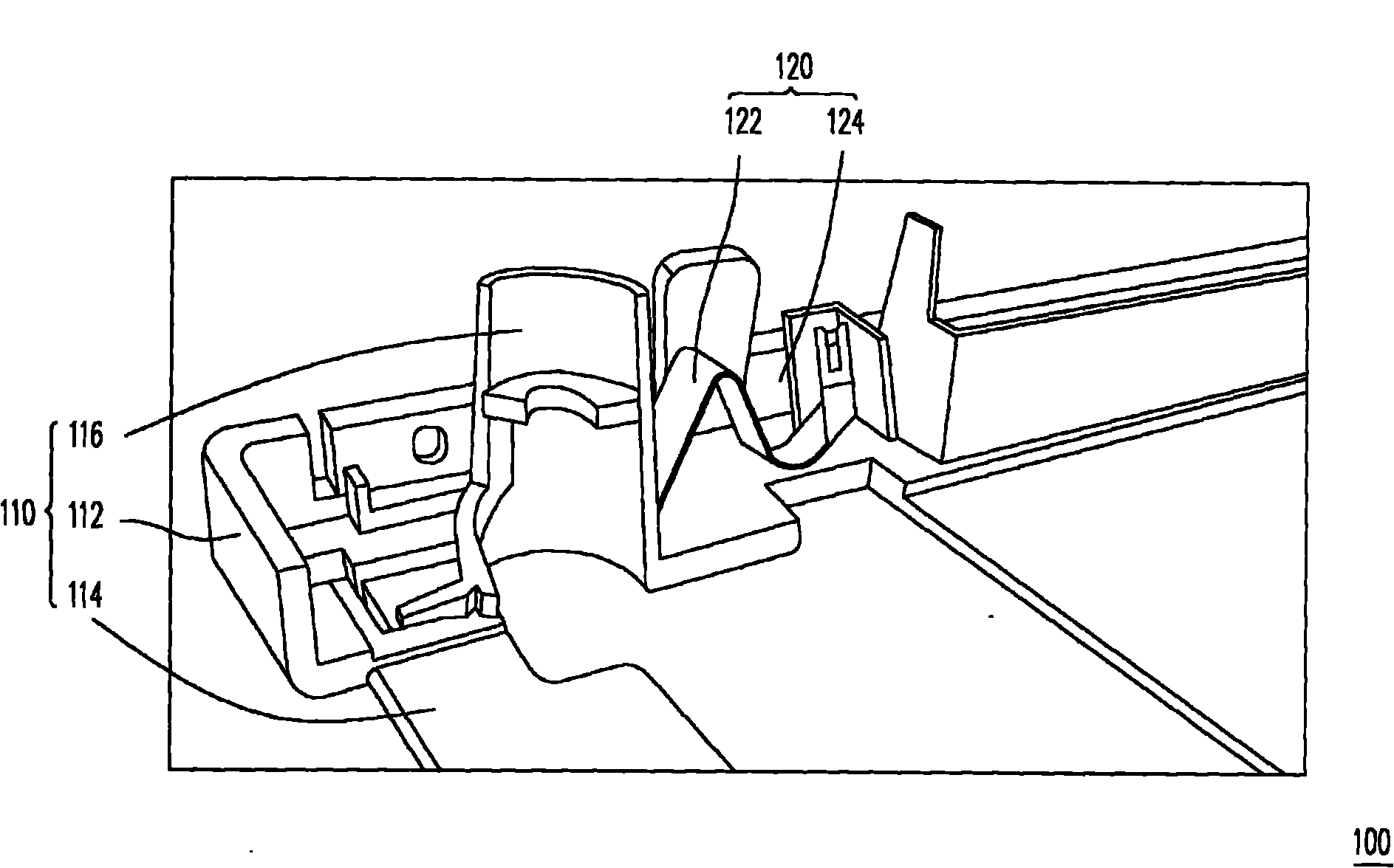
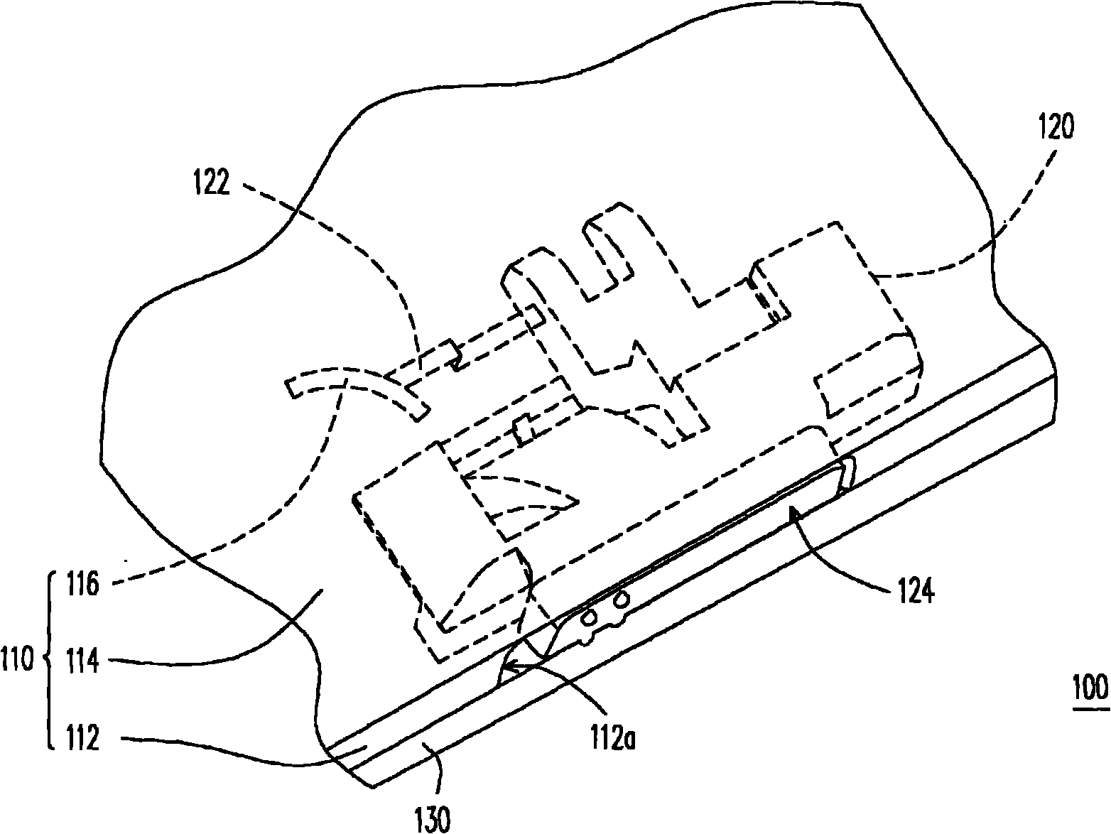
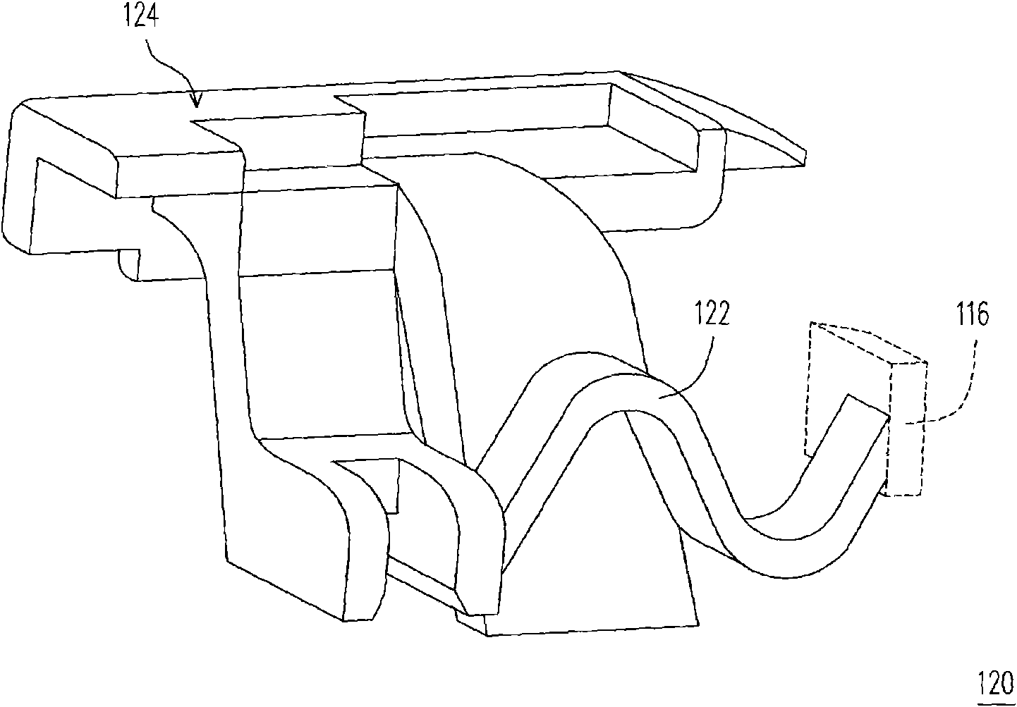
[0024] figure 1 It is a structural schematic diagram of a push button structure according to an embodiment of the present invention, figure 2 is a partial perspective schematic diagram of an electronic device according to an embodiment of the present invention, and image 3 for figure 1 A schematic diagram of the three-dimensional structure of the push button. Please also refer to figure 1 , figure 2 and image 3 , the push button structure 100 of this embodiment is suitable for application in an electronic device (not shown), wherein the electronic device can be a notebook computer or a mobile phone, etc., and the push button structure 100 can be the The latch mechanism or the withdrawing mechanism are linked to achieve the purpose of limiting the relative position of the two components or withdrawing the expansion component such as the memory card from the electronic device.
[0025] As mentioned above, the push button structure 100 includes a first casing 110 and a ...
PUM
 Abstract
Description
Claims
Application Information
 - R&D
- Intellectual Property
- Life Sciences
- Materials
- Tech Scout
- Unparalleled Data Quality
- Higher Quality Content
- 60% Fewer Hallucinations
Browse by: Latest US Patents, China's latest patents, Technical Efficacy Thesaurus, Application Domain, Technology Topic, Popular Technical Reports.
© 2025 PatSnap. All rights reserved.Legal|Privacy policy|Modern Slavery Act Transparency Statement|Sitemap|About US| Contact US: help@patsnap.com


