
Artificial spinal disc implant

A technology of implants and spinal discs, applied in the direction of spinal implants, joint implants, joint implants, etc., can solve the problems that cannot be manifested, the implants are prone to failure, and the implants cannot effectively execute the natural spine. Disk and other issues

Inactive Publication Date: 2011-05-11
RANIER LIMITED
View PDF4 Cites 0 Cited by
  • Summary
  • Abstract
  • Description
  • Claims
  • Application Information

AI Technical Summary

Problems solved by technology

In general, however, such disc implants are limited in their ability to adequately mimic the biomechanics of the average healthy human spinal disc.
For example, such implants do not exhibit adequate resistance to the forces (e.g., bending, twisting, stretching, and compression) that are typically applied to the implant throughout the day
As a result, these implants may not be able to effectively perform the function of the natural spinal disc
Also, the implants may be prone to failure and / or may be dislodged from their position within the spine

Method used


Image

  • Artificial spinal disc implant
  • Artificial spinal disc implant
  • Artificial spinal disc implant

Examples


Embodiment Construction

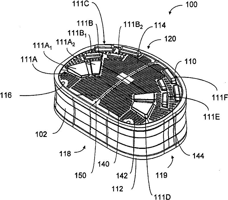
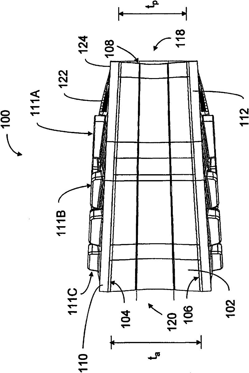
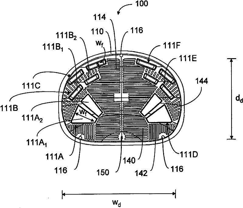
[0022] The present invention provides an artificial spinal disc implant that can be implanted between adjacent vertebrae in the spine to replace, repair or augment a natural spinal disc. A spinal disc implant may be characterized by one or more biomechanical properties that approximate those of a natural spinal disc. The implant can also be designed to be sufficiently fixed to the vertebrae so that it can function long-term in vivo.

[0023] The spinal disc implant may include one or more end plates. The endplates may have an outer surface that includes fixation elements designed to fit into corresponding features (e.g., recesses) on the vertebrae to secure the disc between the vertebrae between. The fixation element may be configured and constructed to provide greater resistance to forces acting to dislodge the disc from its position between the vertebrae. For example, fixation elements may be designed to have certain preferred dimensions and / or may be positioned in certai...


PUM


Abstract

An artificial spinal disc implant (100) is provided that may be implanted between adjacent vertebrae in the spine to replace, repair or augment a natural spinal disc. The spinal disc implant may be characterized by one or more biomechanical properties that approximate those of natural spinal disc. The implant is also designed to be sufficiently secured to the vertebrae so that it may function in the body for long time periods. The endplate of the implant comprises a series of arrangements of fixation elements (111 A-F). The volume of the fixation elements which are closer to the posterior side of the implant is greater than the volume of the other fixation elements.

Description

technical field [0001] The present invention generally relates to artificial spinal disc implants. Background technique [0002] Spinal discs are located between adjacent vertebrae in the spine. This spinal disc stabilizes the spine and helps distribute forces between the vertebrae. The spinal disc includes an outer fibrous annulus that surrounds the inner nucleus pulposus. The fibrous annulus is a concentric layer structure of aligned collagen fibers and fibrous tubes that provide stability against axial torsional and bending forces. The nucleus pulposus includes a gel-like material that distributes stress on the spinal disc. [0003] Spinal discs may be damaged due to trauma, disease, or other degenerative processes that may occur over time. For example, the annulus fibrosus can weaken and / or begin to tear, which can cause the nucleus pulposus to protrude into the region of the spine that includes the spinal nerves (eg, the spinal foramen). A herniated nucleus pulposu...

Claims


Application Information

Patent Timeline
Patent Type & Authority Applications(China)
IPC IPC(8): A61F2/30A61F2/44
CPCA61F2/30771A61F2/442A61F2002/30014A61F2002/3008A61F2002/30112A61F2002/30563A61F2002/30827A61F2002/30884A61F2002/30894A61F2002/3092A61F2230/0004A61F2250/0018A61F2250/0098A61B17/70A61F2/44
Inventor 罗伯特·斯内尔斯科特·约翰逊乔纳森·劳森
Owner RANIER LIMITED
Learn More