Spinal implant system and method

a technology of spine and implant system, applied in the field of spine implant system and a method for treating the spine, can solve the problems of presenting certain challenges in the treatment of techniques, failure to relieve the symptoms of spine disorders,

Active Publication Date: 2018-03-20
WARSAW ORTHOPEDIC INC
View PDF64 Cites 4 Cited by
  • Summary
  • Abstract
  • Description
  • Claims
  • Application Information

AI Technical Summary

Problems solved by technology

Non-surgical treatments, such as medication, rehabilitation and exercise can be effective, however, may fail to relieve the symptoms associated with these disorders.
Certain spinal surgery approac

Method used


Image

  • Spinal implant system and method
  • Spinal implant system and method
  • Spinal implant system and method

Examples


Embodiment Construction

[0035]The exemplary embodiments of the surgical system and related methods of use disclosed are discussed in terms of medical devices for the treatment of musculoskeletal disorders and more particularly, in terms of a surgical system for implant delivery to a surgical site and a method for treating a spine, which employ an oblique surgical pathway, which may include an oblique-lateral surgical pathway. In one embodiment, the systems and methods of the present disclosure are employed with a spinal joint and fusion, for example, with a cervical, thoracic, lumbar and / or sacral region of a spine.

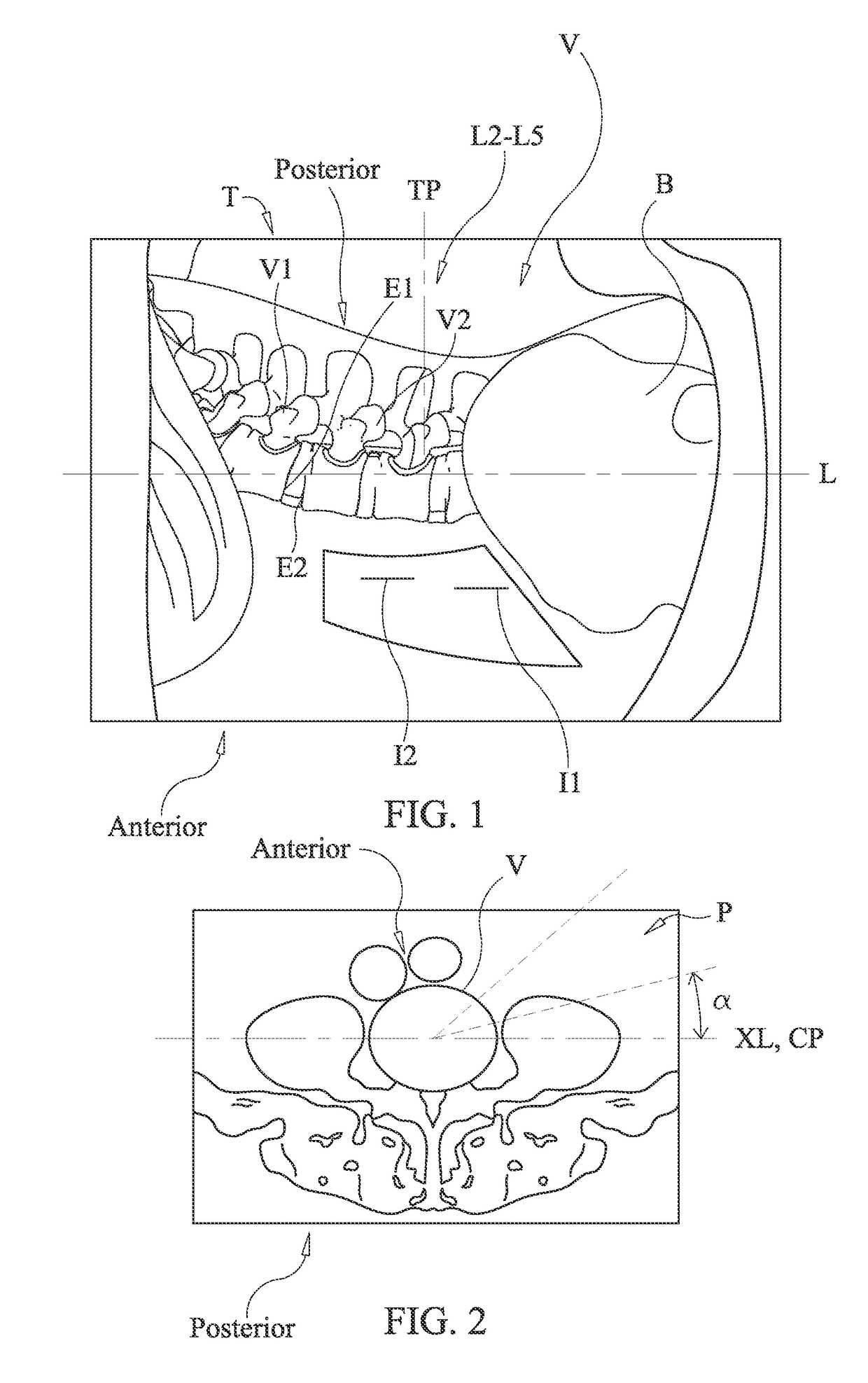
[0036]In one embodiment, the surgical system is employed with a method including an oblique lateral interbody fusion (OLIF) procedure in the lower lumbar region between an L1 vertebral body and an L5 vertebral body using an antero-lateral operative corridor between a lateral psoas muscle and an anterior vasculature, such as, for example, the vena cava and aorta. In one embodiment, the patient is...


PUM


Abstract

A spinal implant comprises an implant body extending between an anterior surface and a posterior surface and includes a first vertebral engaging surface and a second vertebral engaging surface. The implant body includes an inner surface that defines at least one cavity that is oriented to implant a fastener oblique relative to a lateral axis of a subject body and adjacent an intervertebral space of the subject body. The implant body includes an oblique surface that defines at least one opening disposed in substantial alignment with the at least one cavity. Systems and methods are disclosed.

Description

CROSS-REFERENCE TO RELATED APPLICATION[0001]This application claims the benefits of U.S. Provisional Patent Application No. 61 / 887,794 filed Oct. 7, 2013, the contents of which being hereby incorporated in its entirety by reference.TECHNICAL FIELD[0002]The present disclosure generally relates to medical devices for the treatment of musculoskeletal disorders, and more particularly to a spinal implant system and a method for treating a spine, which employ an oblique pathway.BACKGROUND[0003]Spinal pathologies and disorders such as scoliosis and other curvature abnormalities, kyphosis, degenerative disc disease, disc herniation, osteoporosis, spondylolisthesis, stenosis, tumor, and fracture may result from factors including trauma, disease and degenerative conditions caused by injury and aging. Spinal disorders typically result in symptoms including deformity, pain, nerve damage, and partial or complete loss of mobility.[0004]Non-surgical treatments, such as medication, rehabilitation a...

Claims


Application Information

Patent Timeline
IPC IPC(8): A61F2/44A61B17/70A61B17/02A61F2/46A61B17/80A61B17/00A61F2/30A61B34/20A61B90/00
CPCA61F2/442A61B17/7059A61B17/8042A61F2/447A61F2/4455A61F2/4465A61F2/4611A61F2/4684A61B17/0206A61F2310/00359A61B2017/00004A61B2034/2055A61B2090/3966A61F2002/3008A61F2002/30092A61F2002/30578A61F2002/30787A61F2002/30904A61F2002/4475A61F2220/0016A61F2310/00017A61F2310/00023A61F2310/00029A61F2310/00293A61F2002/30593A61F2002/4668A61F2002/4658
Inventor WAUGH, LINDSEY G.MELKENT, ANTHONY J.BLACKWELL, JONATHAN E.DROCHNER, THOMAS E.GOWAN, CARRIE L.WILFONG, BRET MATTHEWCARLS, THOMAS A.HYNES, RICHARD A.SILCOX, III, D. HALCOWAN, JR., JOHN A.MOBASSER, JEAN-PIERRE
Owner WARSAW ORTHOPEDIC INC
Why Eureka
Try Eureka