Lower cutter for shaving heads for dry razors

A lower cutter and cutter technology, applied in metal processing and other directions, can solve problems such as damage to perforated metal sheets, uneven distribution of mechanical stress, loss of direct contact, etc., and achieve the effect of ensuring permanence and eliminating notch effects.

Active Publication Date: 2016-10-19
BRAUN GMBH
View PDF6 Cites 0 Cited by
  • Summary
  • Abstract
  • Description
  • Claims
  • Application Information

AI Technical Summary

Problems solved by technology

[0005] Undercutter designs according to the known type have the disadvantage that they generate a high frictional resistance due to the viscous friction between the perforated sheet metal and the friction surface of the associated undercutter
This results in high energy consumption and, for the user, the heated shaving element is uncomfortable and wears prematurely
Because of the uneven distribution of mechanical stress over the individual blade lengths, these protrusions are uneven over the entire length of the blade due to the forces generated when the shaving head is pressed against the user's skin
This results in a partial loss of direct contact between the lower cutter and the perforated foil, so hairs that have passed through the perforated foil are not cut but just pulled in, which results in painful pulling of the hair from the skin
Also, the uneven protrusion of the blade can damage the perforated foil

Method used


Image

  • Lower cutter for shaving heads for dry razors
  • Lower cutter for shaving heads for dry razors
  • Lower cutter for shaving heads for dry razors

Examples


Embodiment approach

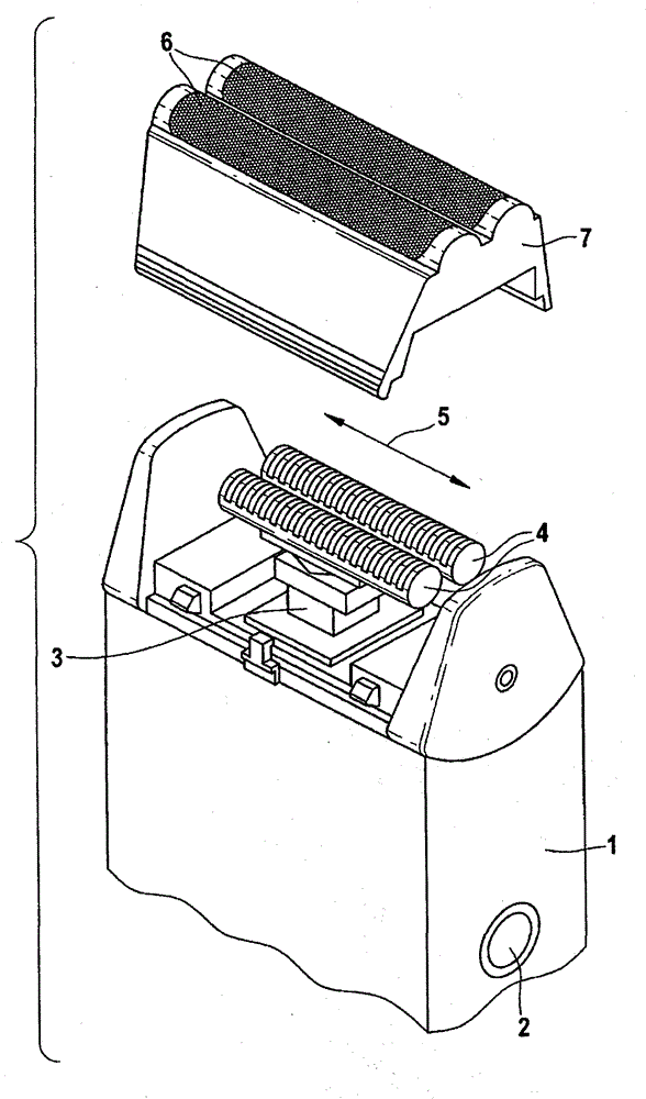
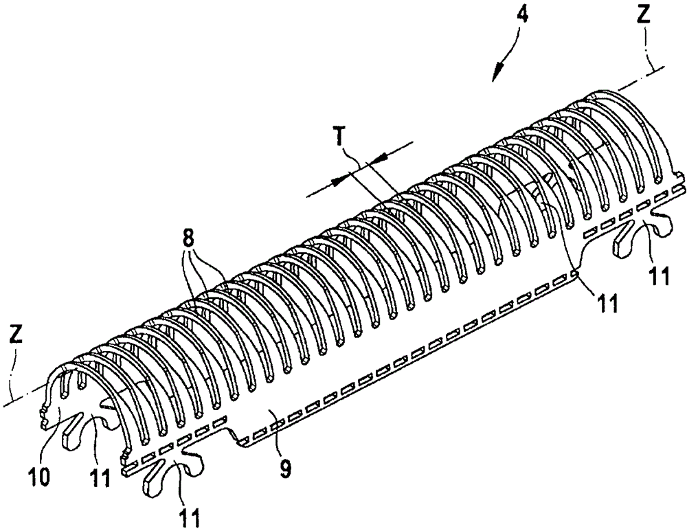
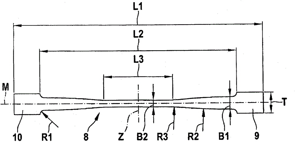
[0021] figure 2 The shown lower cutter 4 according to the invention has a plurality of U-shaped blades 8 extending parallel to each other, which extend in the form of strips between two peripheral regions 10 and 9 . These two peripheral areas 9 and 10 each have a mounting portion 11 at their front and rear ends for connection to a support member, details of which are not shown in the figures, which ultimately serve to connect the lower cutter 4 to the dry razor Action on drive element 3. The longitudinal extent of each peripheral region 9 and 10 between its two mounting parts 11 corresponds to the direction of vibration according to the double arrow 5 . According to the exemplary embodiment shown here, the blade 8 extends perpendicularly to the longitudinal extent of the peripheral regions 9 , 10 . The width of the blades 8 and the distance between the blades of the lower cutter 4 are measured parallel to the longitudinal extent of the peripheral area.

[0022] as in fig...


PUM


Abstract

The invention relates to a lower cutter (4) which together with an associated upper cutter (6) forms the shaving head of a dry razor. The upper cutter is designed in the form of a perforated metal sheet (6) which at least partially surrounds the lower cutter (4) and is prestressed against it. The lower cutter (4) has a plurality of spaced apart blades with cutting edges (12, 13) in the form of a strip between two peripheral regions (9, 10). The cross-section of the lower cutter (4) is substantially U-shaped. The width of the strip tapers monotonically in the direction of the center (Z) starting from the two peripheral regions (9, 10).

Description

technical field [0001] The invention relates to a lower cutter which together with an associated upper cutter forms the shaving head of a dry razor according to the preamble of claim 1 . Background technique [0002] An undercutter of this type is already known from US 7,022,195 B2, wherein such an undercutter consists of a plurality of strip-shaped blade elements having a constant width or increasing width towards the centre. [0003] Such cutters are located within the shaving head of a dry razor, are driven in an oscillating manner, are pressed against a perforated foil, and are subjected to complex loads during shaving. [0004] For example, they function by contact pressure with which the user presses the razor against the skin, subjecting the bar blades to bending loads about an axis corresponding to the blade width. During hair cutting, due to the cutting force, an additional mechanical load occurs which is a bending load at the apex and becomes a compound load consi...

Claims


Application Information

Patent Timeline
Patent Type & Authority Patents(China)
IPC IPC(8): B26B19/04
CPCB26B19/044
Inventor 莱茵霍尔德·艾科霍恩安德烈亚斯·哈特曼彼得·琼克乔基姆·克劳斯迈克尔·奥德莫安德烈亚斯·彼得索斯滕·波尔马库斯·萨比希托拜厄斯·施瓦兹托马斯·弗斯特格于尔根·沃尔夫克里斯托夫·泽古拉
Owner BRAUN GMBH
Why Eureka
Try Eureka