
Fiber optic furcation assembly

A bifurcation and optical fiber technology, applied in optical components, light guides, optics, etc., can solve problems such as micro-bending of optical fibers, transmission loss, and damage to optical fibers

Inactive Publication Date: 2014-11-19
TYCO ELECTRONICS NETHERLAND BV
View PDF13 Cites 0 Cited by
  • Summary
  • Abstract
  • Description
  • Claims
  • Application Information

AI Technical Summary

Problems solved by technology

These strains, especially bending strains, can cause damage to the fiber, causing microbending of the fiber and transmission loss

Method used


Image

  • Fiber optic furcation assembly
  • Fiber optic furcation assembly
  • Fiber optic furcation assembly

Examples


Embodiment Construction

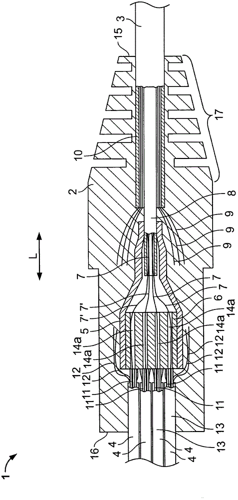
[0054] will now refer to figure 1 Preferred embodiments of the present invention are described.

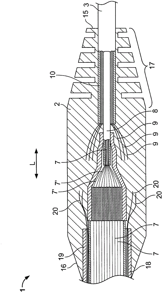
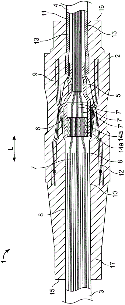
[0055] The furcation assembly 1 comprises an overmolded body 2 enclosing a distribution fiber optic cable 3 and a furcation fiber optic cable 4 formed as a plurality of loose tube individual fiber optic cables 4 . The furcation assembly 1 also includes a protection tube 5 and a fiber guiding element 6 .

[0056] The fiber optic cable 3 extends into the overmolded body 2 along the longitudinal direction L. As shown in FIG. The optical cable 3 includes a plurality of optical fibers 7 . The optical fiber 7 is surrounded by a buffer tube 8 . Advantageously, the cable 3 has a set of strength members 9, preferably made of aramid. The housing 10 covers the fiber optic cable and protects the fiber optic cable from environmental pollution.

[0057] A single fiber optic cable 4 also extends into the overmolded body 2 in the longitudinal direction, but opposite the fiber optic cable 3 ....


PUM


Abstract

The invention relates to a fiber optic furcation assembly (1) which comprises an over-molded body (2) formed from a flexible material, having a first end (15) and an opposed second end (16), the first end (15) being adapted to receive a portion of a fiber optic distribution cable (3) having at least two optical fibers (7), and the second end (16) being adapted to receive a portion of at least one furcation cable jacket (13) sheathing at least one furcated optical fiber (7') from the fiber optic distribution cable (3), at least one of the fiber optic distribution cable (3) and the furcation cable jacket (13) comprising reinforcement members (9, 12). To reduce the load of the optical fibers (7) within the furcation assembly at least a portion of the reinforcement members (9, 12) is anchored within the over-molded body (2) so as to transmit a load from the over-molded body via the anchored reinforcement members (9, 12) to the respective cable (3, 4).

Description

technical field [0001] The present invention relates to an optical fiber furcation assembly comprising an overmolded body formed of a flexible material, the overmolded body having a first end and an opposite second end, the first end being adapted to receive an optical fiber cable having at least two optical fibers The second end is adapted to receive a portion of at least one furcation cable jacket covering at least one furcation optical fiber from the cable, at least one of the distribution cable and the furcation cable jacket including a strength member. Background technique [0002] Fiber optic cables can be used in many physical variations. For example, there are single and multiple fiber constructions, aerial cables and direct burial cable types. Typically, a sheath of PVC or similar material is extruded over the cable to protect the interior of the cable from the environment. These fibers are protected with loose-fit tubing or tight-fit buffer coatings. In the loos...

Claims


Application Information

Patent Timeline
Patent Type & Authority Patents(China)
IPC IPC(8): G02B6/44
CPCG02B6/4477G02B6/4472
Inventor 希奥·范德缪伦保罗·施耐德弗兰兹·范盖恩
Owner TYCO ELECTRONICS NETHERLAND BV
Learn More