

Communication device and wireless communication system
A technology for a wireless communication system and a communication device, applied in the field of wireless communication systems, can solve problems such as low transmission power, achieve the effects of efficient frequency management, improve data transmission efficiency, and improve frequency utilization efficiency
- Summary
- Abstract
- Description
- Claims
- Application Information
AI Technical Summary
Problems solved by technology
Method used
Image

Examples
Embodiment approach 1
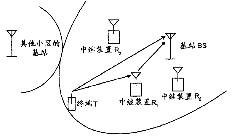
[0068] figure 1 It is a diagram showing a configuration example and a basic signal transmission operation of the wireless communication system according to the present embodiment. figure 1 The shown wireless communication system includes: a terminal T as a communication device on the transmitting side; a base station BS as a communication device on the receiving side; Device R 1 , R 2 , R 3 ). In addition, as long as the terminal T and each of the relay devices R is a wireless device, any of a mobile terminal, a terminal constantly connected to a power source, and a personal computer may be used. exist figure 1 , showing the relay device R 1 A case where a signal transmitted from the terminal T is relayed.
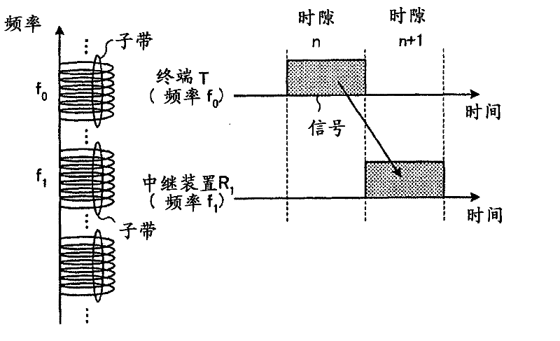
[0069] in addition, figure 2 It is a diagram showing an example of the relationship between the timing of signal transmission by the terminal T and the relay device R in the wireless communication system according to the present embodiment and the wireless reso...
Embodiment approach 2
[0090] Next, Embodiment 2 will be described. In Embodiment 1, relay transmission by a single relay device was mainly described, but in this embodiment, relay transmission by a plurality of relay devices will be described. In addition, the configuration of each relay device is the same as that of the relay device shown in Embodiment 1 (refer to Figure 4 )same.
[0091] Figure 7 It is a diagram showing a configuration example of a radio communication system according to Embodiment 2 and basic signal transmission operations. in addition, Figure 8 It is a diagram showing an example of relay transmission according to Embodiment 2, and more specifically, it is a diagram showing signal transmission operations of the terminal T and each relay device R and radio resources used at this time. in addition, Figure 7 The configuration and embodiment 1 of the wireless communication system shown (refer to figure 1 )same.
[0092] Below, according to Figure 7 as well as Figure ...
Embodiment approach 3
[0098] Next, Embodiment 3 will be described. In Embodiment 2, relay transmission by a plurality of relay devices was described. In this embodiment, relay transmission by a relay device having a plurality of antennas (multiple transmission / reception systems) is described. In addition, the configuration of the relay device according to the present embodiment is the same as that of the relay device according to Embodiment 1 except that it has a plurality of antennas. For example, with the same number of antennas Figure 4 Transmit / receive system shown.
[0099] Figure 9 It is a diagram showing an example of relay transmission according to Embodiment 3, more specifically, it shows a relay device R including a terminal T and a plurality of antennas 1 A diagram of the signaling operation and the radio resources used at this time. In Embodiment 2, a structure in which each relay device performs relay transmission using a different frequency is applied, but it is also possible to...
PUM
 Abstract
Description
Claims
Application Information