Auxiliary roller

A technology of auxiliary roll and roll body, applied in metal processing equipment, metal rolling, manufacturing tools, etc., can solve the problems of large occupied space and high cost, and achieve the effect of saving space, simplifying structure and optimizing design.

Inactive Publication Date: 2011-05-18
CHINA NON-FERROUS METALS PROCESSING TECH CO LTD
View PDF5 Cites 0 Cited by
  • Summary
  • Abstract
  • Description
  • Claims
  • Application Information

AI Technical Summary

Problems solved by technology

This transmission method requires components such as hydraulic motor, chain transmission part, roller body, roller body support part, hydraulic motor and roller body mounting seat, etc. The number of parts required to realize the roller body work is large and the cost is high. The size of the occupied space is relatively large

Method used


Image

  • Auxiliary roller
  • Auxiliary roller
  • Auxiliary roller

Examples


Embodiment Construction

[0021] The technical solution of the present invention will be further described in detail below through the drawings and embodiments.

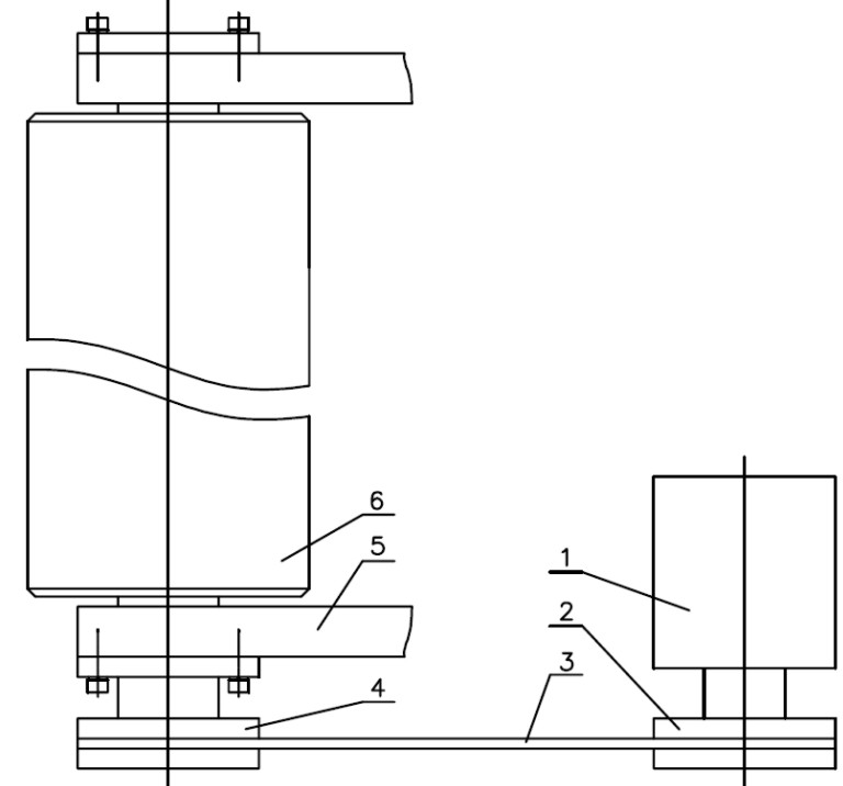
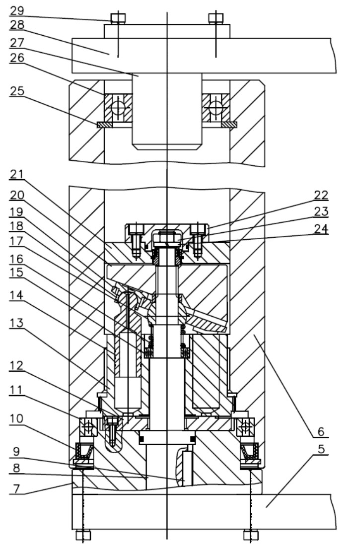
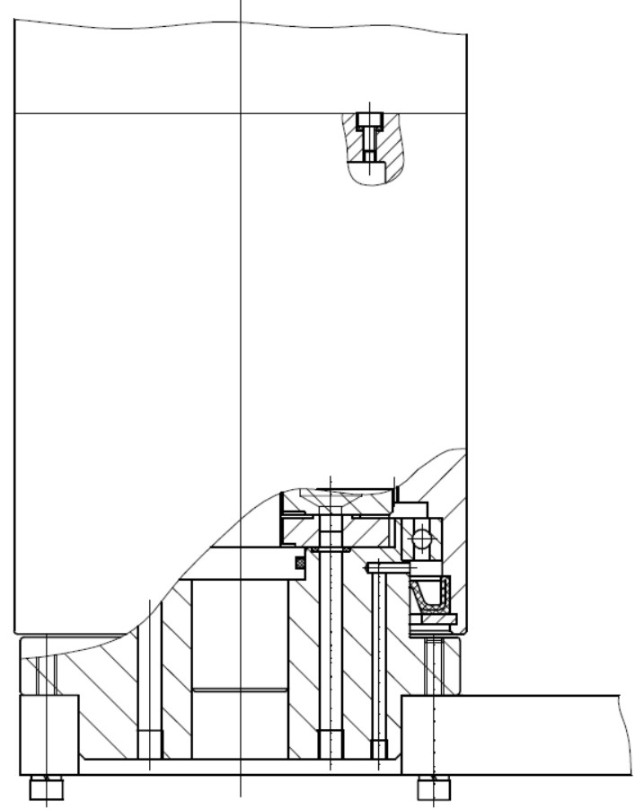
[0022] Such as figure 2 , 3 As shown, the auxiliary roller according to the present invention includes a roller body 6 and a driving device thereof. The driving device includes a base 7 and a rotary driving part installed on the base; the rotary driving part is arranged inside the roller body and extends into the roller body The lower end of the roller body 6 is connected with the base 7; the rotating drive part mainly includes a fixed spindle 8, an oil distribution plate 12, a cylinder 13, a plunger group, a return mechanism and a return disc 20. The central part of the cylinder is installed There is a second bearing 15, the fixed spindle 8 passes through the center of the cylinder 13, and the lower end is installed on the base 7; the oil distribution plate is used to separate the high and low pressure oil chambers of the rotating drive part, a...


PUM


Abstract

The invention discloses an auxiliary roller, comprising a roller body and a driving device of the roller body. the driving device comprises a base and a rotating driving part arranged on the base and in the roller body; the lower end of the roller body is connected with the base; the roller body serves as both a working device and a shell of the rotating driving part in the roller body; and the rotating driving part drives the roller body to rotate and work. Because the roller body serves as both the working device and the shell of the driving device in the roller body and integrates the working part and the driving part, the structure of the roller body is greatly simplified, the number of parts for realizing the work of the roller body is reduced, and the optimal design of the auxiliary roller is realized.

Description

Technical field [0001] The invention relates to a roller, in particular to an auxiliary roller driven by a driving device for processing equipment in the steel and non-ferrous metal processing industries. Background technique [0002] The processing equipment in the steel and non-ferrous metal processing industries has many auxiliary rollers, and the rotary drive of each auxiliary roller is currently mainly driven by hydraulic motors or electric motors. In the prior art, the structure of the auxiliary roller driving device is as figure 1 As shown, it includes a hydraulic motor 1, a driving sprocket 2, a chain 3, a driven sprocket 4, a supporting arm 5, and a roller body 6, which is rotated by a hydraulic motor, and the roller body is driven to rotate through a chain drive. This type of transmission requires parts such as hydraulic motor, chain transmission part, roller body, support part of the roller body, hydraulic motor and the mounting seat of the roller body, etc., which req...

Claims


Application Information

Patent Timeline
Patent Type & Authority Applications(China)
IPC IPC(8): B21B39/00B21B39/12
Inventor 许小丰韩吕昌
Owner CHINA NON-FERROUS METALS PROCESSING TECH CO LTD
Why Eureka
Try Eureka