Automatic hydraulic mudjacking machine

A hydraulic and automatic technology, applied in the direction of presses, manufacturing tools, etc., can solve the problems of slow discharge, time-consuming and laborious, etc., and achieve the effect of simplifying the grouting method

Inactive Publication Date: 2011-05-18
周毅勇
View PDF5 Cites 14 Cited by
  • Summary
  • Abstract
  • Description
  • Claims
  • Application Information

AI Technical Summary

Problems solved by technology

[0002] At present, the traditional grouting method usually uses auxiliary tools such as wooden sticks, jacks, etc. to squeeze the pulp placed in the bag by beating and pressi

Method used


Image

  • Automatic hydraulic mudjacking machine
  • Automatic hydraulic mudjacking machine
  • Automatic hydraulic mudjacking machine

Examples


Embodiment Construction

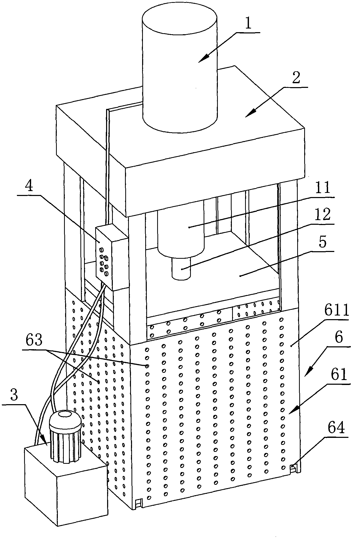
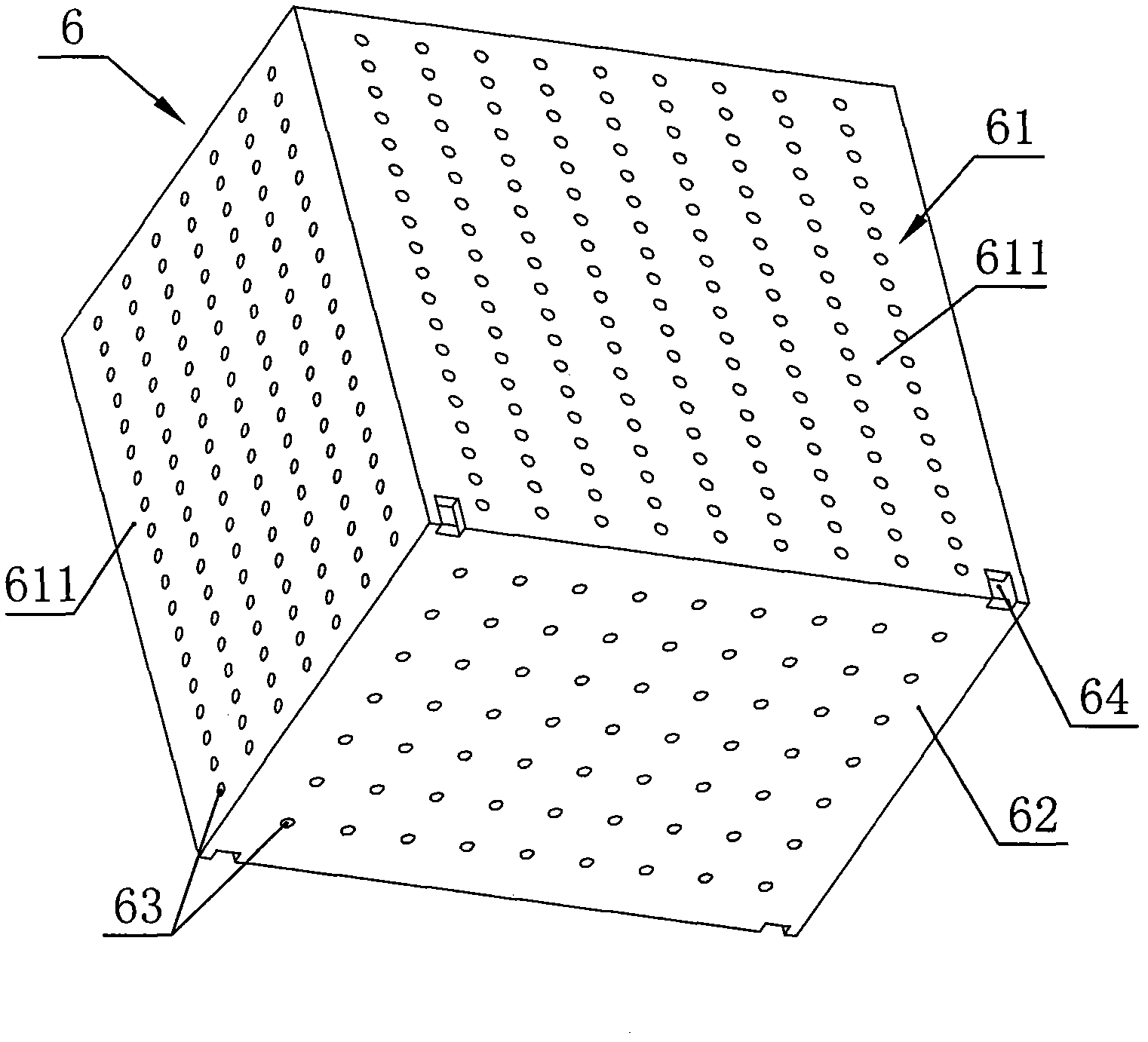
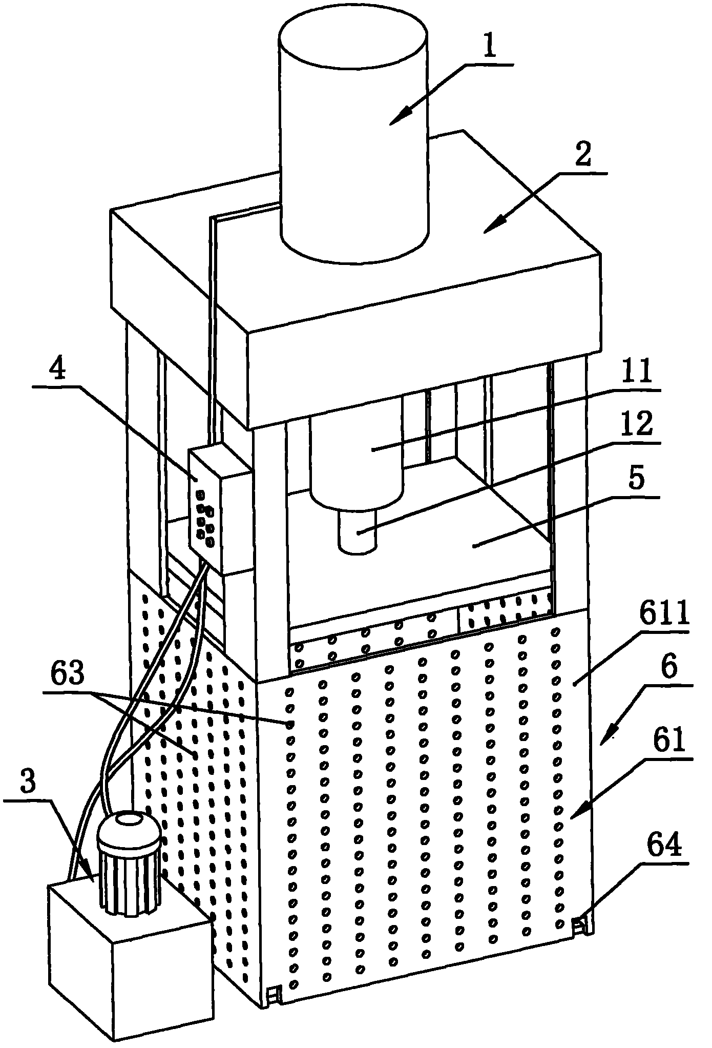
[0011] Such as figure 1 , 2 Shown is an automatic hydraulic grouting machine, including a hydraulic cylinder 1, a hydraulic cylinder base 2, a hydraulic oil pump 3 and a control device 4, the hydraulic cylinder 1 is fixed on the hydraulic cylinder base 2, and the hydraulic oil pump 3 serves as a hydraulic The power source of the oil cylinder 1, a control device 4 is provided between the hydraulic oil pump 3 and the hydraulic oil cylinder 1, the hydraulic oil cylinder 1 includes a cylinder body 11 and an output shaft 12, and the output end of the output shaft 12 is fixed with a pressure plate 5, An accommodating housing 6 is provided below the pressing plate 5, the accommodating housing 6 includes a side wall 61 and a bottom plate 62, the side wall 61 is surrounded by four side plates 611, and the side plates 611 and the bottom plate 62 are provided with several drainage holes 63 , and a plurality of drainage grooves 64 are also provided at the connection between the side plat...


PUM


Abstract

The invention discloses an automatic hydraulic mudjacking machine which comprises a hydraulic cylinder, a hydraulic cylinder base, a hydraulic oil pump and a control device, wherein the hydraulic cylinder is fixed on the hydraulic cylinder base; the hydraulic oil pump serves as a power source of the hydraulic cylinder; the control device is arranged between the hydraulic oil pump and the hydraulic cylinder; the hydraulic cylinder comprises a cylinder body and an output shaft; and the output end of the output shaft is fixedly provided with a pressing plate, so that the automatic hydraulic mudjacking machine is suitable for extruding various pulp products, thus the water of the products can be drained quickly. Because the traditional manual mudjacking method is replaced by the fully automatic hydraulic machine, the original mudjacking mode of time and labor waste is simplified, time and labor are saved, and the quantity of extrudable pulp at one step is increased greatly compared with that of the prior art. In addition, an accommodating shell is additionally arranged below the mudjacking machine, so that bags for storing the pulp are more convenient to place; and simultaneously, a drain hole and a drain tank are additionally arranged on the accommodating shell, thus the water drained from the pulp can flow quickly out of the accommodating shell.

Description

technical field [0001] The invention relates to a grouting machine, in particular to an automatic hydraulic grouting machine. Background technique [0002] At present, the traditional grouting method usually uses auxiliary tools such as wooden sticks, jacks, etc. to squeeze the pulp placed in the bag by beating and pressing, so that the water inside is slowly discharged. The method is not only time-consuming and laborious, but also can only squeeze a small amount of pulp at a time. Contents of the invention [0003] Aiming at the deficiencies of the prior art, the present invention provides a fully automatic automatic hydraulic pulp press machine with a large amount of pulp squeezed at one time. [0004] In order to achieve the above object, the present invention provides an automatic hydraulic grouting machine, comprising a hydraulic cylinder, a hydraulic cylinder base, a hydraulic oil pump and a control device, the hydraulic cylinder is fixed on the hydraulic cylinder b...

Claims


Application Information

Patent Timeline
IPC IPC(8): B30B9/06
Inventor 周毅勇
Owner 周毅勇
Why Eureka
Try Eureka