Diaphragm wall joint and manufacturing method of diaphragm wall

An underground diaphragm wall and its manufacturing method technology, which are applied in the field of underground diaphragm wall joints and its manufacture, can solve the problems of easy water gushing and sand gushing, delay in construction period, and unclean foam filling, and achieve good terrain adaptability and avoid water gushing Good effect of sand and water stop

Inactive Publication Date: 2011-05-18
GUANGDONG FOUND ENG GRP CO LTD
View PDF5 Cites 17 Cited by
  • Summary
  • Abstract
  • Description
  • Claims
  • Application Information

AI Technical Summary

Problems solved by technology

However, the initial setting time of the concrete must be well grasped during the pullout period of the circular joint. If the pullout is too fast, the concrete will fill the space in the joint. If the pullout is too slow, the joint will break or mud will be trapped, and water and sand gushing will easily occur; The form of the beam joint is to wash away the foam filler filled on the I-beam web due to construction needs before the connection, and then grout the connect

Method used


Image

  • Diaphragm wall joint and manufacturing method of diaphragm wall
  • Diaphragm wall joint and manufacturing method of diaphragm wall
  • Diaphragm wall joint and manufacturing method of diaphragm wall

Examples


Embodiment Construction

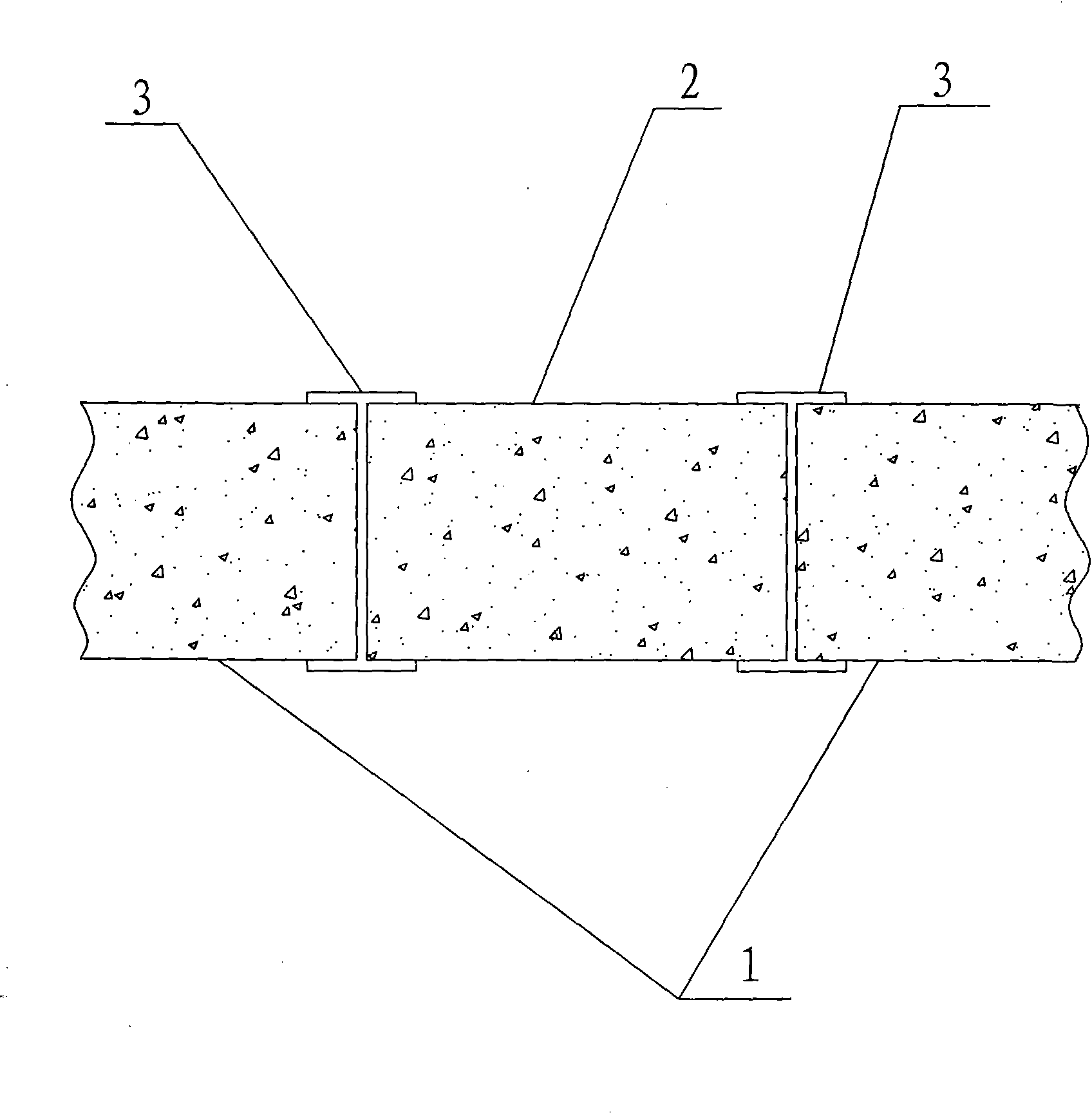
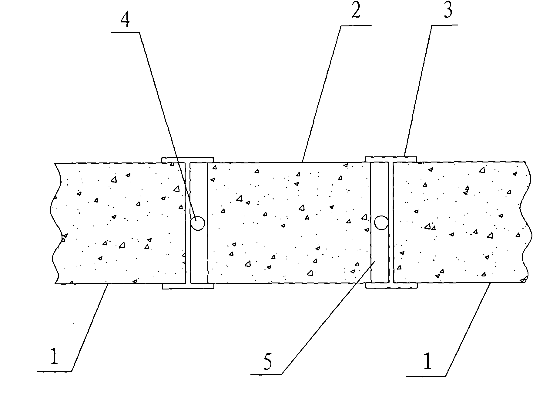
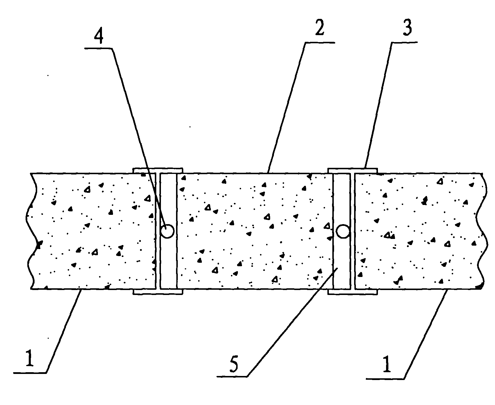
[0021] refer to figure 1 , an underground diaphragm wall joint, which includes two sections of first-stage walls 1 placed in the same foundation pit with opposite sides, and the opposite sides of the two sections of first-stage walls 1 are respectively connected with two I-beams 3 webs are fixedly connected, and the foundation pit in the middle of the two I-beams 3 is provided with a second-stage wall 2, and a sleeve valve pipe is passed between the second-stage wall 2 and the webs of the I-beams 3 4 Fill the cement slurry connection.

[0022] As a further preferred embodiment, the second-phase wall body 2 is a concrete poured reinforcement cage structure. This structure facilitates the formation of the second-phase wall body 2 in the foundation pit, and meets the requirements of watertight and leakproof.

[0023] Further as a preferred embodiment, the sleeve valve tube 4 is a re-injectable sleeve valve tube.

[0024] A method for making an underground connecting wall joint...


PUM


Abstract

The invention discloses a diaphragm wall joint and a manufacturing method of a diaphragm wall. The diaphragm wall joint comprises two sections of first-stage walls in one foundation pit, wherein the sides of the two sections of walls are opposite; the opposite sides of the first-stage walls are respectively and fixedly connected with two joist steel webs; one section of second-stage wall is arranged in a middle foundation pit; and the second-stage wall is connected with the joist steel webs by adopting a sleeve valve tube for grouting. The manufacturing method of the diaphragm wall aims to manufacture the diaphragm wall. For the diaphragm wall joint, the second-stage wall is utilized to transit; the connecting position is fixed by the joist steels and grouted by a sleeve valve tube, thus having good structure adaptability, no water leakage, low possibility of water burst and sand burst, good water-stopping effect, and safety and reliability. In the manufacturing method, substage grouting is carried out on wall sections in the joint, and the fillers of the joist steel webs are washed and then grouted, thus realizing fast forming and firm connection for the joint, and avoiding the water burst and the sand burst.

Description

technical field [0001] The invention relates to an underground continuous wall joint in the field of engineering construction and a manufacturing method thereof. Background technique [0002] When carrying out underground engineering and deep foundation construction, it is usually necessary to build an underground diaphragm wall. The underground diaphragm wall is a narrow and deep foundation pit dug underground with the help of various grooving machines and the wall protection function of mud, and pouring appropriate materials in it to form a seepage-proof, soil-retaining and load-bearing function. Continuous underground walls. Generally speaking, the underground continuous wall is constructed in sections and periods according to the actual construction environment, so there are many sections of discontinuous walls, and finally these discontinuous walls need to be connected by various pouring methods. This structure is called a diaphragm wall joint. At present, there are ...

Claims


Application Information

Patent Timeline
IPC IPC(8): E02D29/16E02D29/02
Inventor 谢永生吴健刘智张明德陈伟仁
Owner GUANGDONG FOUND ENG GRP CO LTD
Why Eureka
Try Eureka