Continuous wall I-steel joint with water-swellable water-stopping strips

A water-swelling, I-beam technology, applied in water conservancy projects, artificial islands, underwater structures, etc., can solve the problems of increasing water seepage paths, high cost, and large amount of steel plates

Active Publication Date: 2017-12-29
CHINA RAILWAY LIUYUAN GRP CO LTD
View PDF3 Cites 4 Cited by
  • Summary
  • Abstract
  • Description
  • Claims
  • Application Information

AI Technical Summary

Problems solved by technology

[0003] The cross steel plate joint is composed of cross steel plate and sliding plate joint box. It is used when there are special requirements for the overall rigidity or anti-seepage of the underground diaphragm wall. Its advantages are: 1) The steel plate is set in the middle of the joint, which increases the water seepage path and prevents leakage. Good performance; 2) Good shear resistance; its disadvantages are: 1) There are many processes, complex construction, and difficult; 2) It is difficult to brush the wall and remove the mud on the side wall of the wall section; 3) The bending resistance is not ideal ; 4) The amount of steel plate used at the joint is relatively large, and the cost is relatively high
However, the joints between the I-beam and the concrete of the second-stage continuous wall cannot be installed with water-expandable water-stop strips like the construction joints of the open-cut underground structure, because the excavation of the foundation groove of the second-stage continuous wall and the brushing of the I-beam wall will damage the joint. The water-swelling water-stop strip, and it takes more than 10 days from the insertion of the I-beam into the first-stage continuous wall foundation groove to the second-stage continuous wall concrete pouring. The water-swellable water-stop strip will swell prematurely before the concrete is poured, losing Expansion water stop function

Method used


Image

  • Continuous wall I-steel joint with water-swellable water-stopping strips
  • Continuous wall I-steel joint with water-swellable water-stopping strips
  • Continuous wall I-steel joint with water-swellable water-stopping strips

Examples


Embodiment

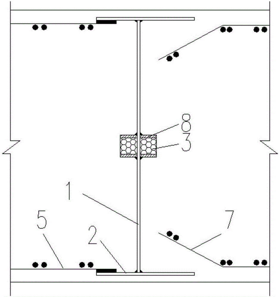
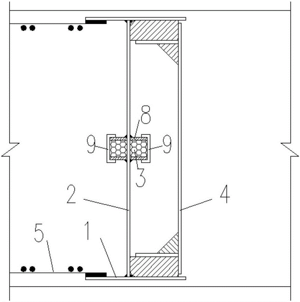
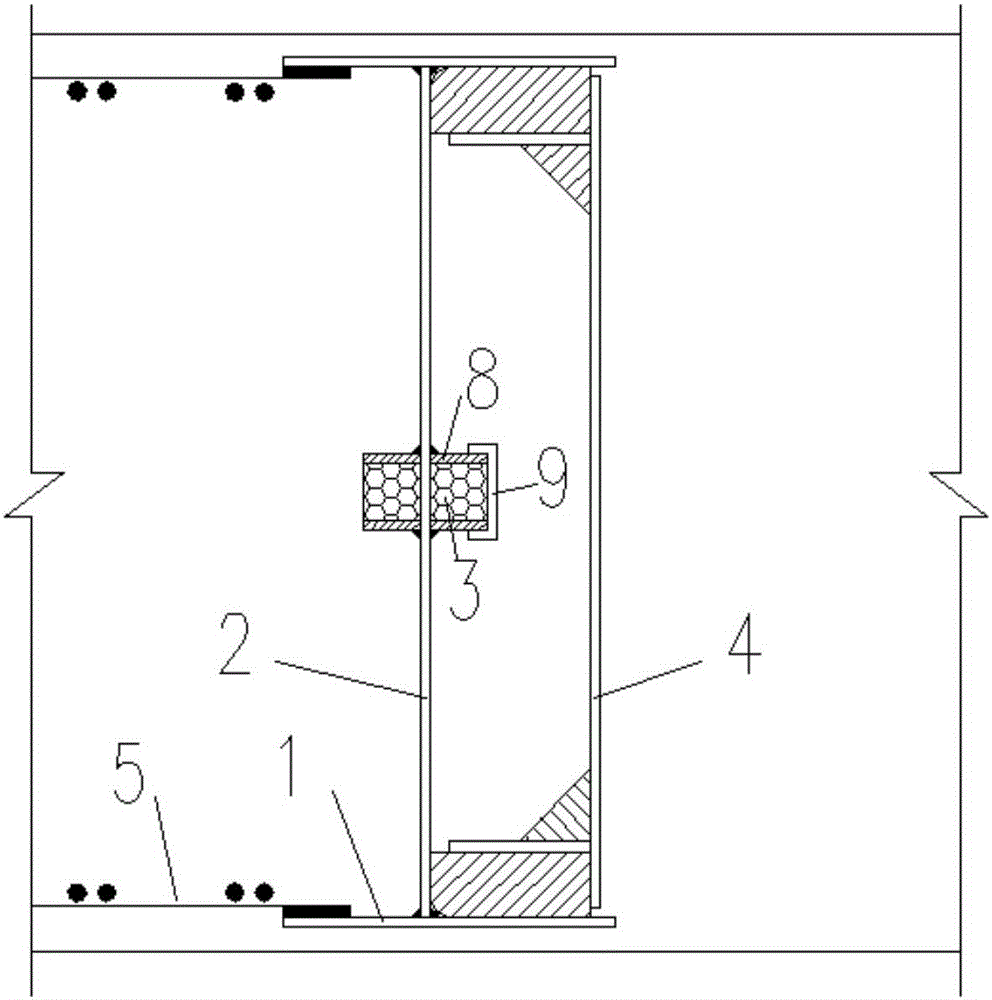
[0052] The site geology of a subway station consists of plain fill, silt, silt and medium sand from top to bottom. The water level of the site is relatively high, and there are multi-storey buildings near the foundation pit. more sensitive. After comparative analysis, the foundation pit enclosure structure adopts underground diaphragm wall + multi-channel internal support, the thickness of diaphragm wall is 1000mm, the vertical length of diaphragm wall is 40m, and the width of diaphragm wall section in standard section is 6m. Diaphragm wall I-beam joints for water-swellable waterstops.

[0053] Diaphragm wall is divided into according to the sequence of construction: first-stage continuous wall section, second-stage continuous wall section, first-stage continuous wall section, second-stage continuous wall section..., the first-stage continuous wall section is constructed first, and the concrete strength of the first-stage continuous wall section is waited After the design str...


PUM


Abstract

The invention relates to a continuous wall I-steel joint with water-swellable water-stopping strips, and relates to the technical field of underground continuous wall engineering in a foundation pit support structure. An I-steel comprises web plates and a wing plate located on the two sides of the web plates; the I-steel is arranged at the two ends or one end of a first-stage underground continuous wall section, a horizontal steel bar of the first-stage underground continuous wall section is welded with the wing plate of the I-steel; the middle of the two sides of the web plates or the middle of one sides of the web plates are vertically provided with water-swellable water-stopping strips, flat steels are arranged on the two sides of the water-swellable water-stopping strips, and the flat steels and the web plates of the I-steel are welded and fixed; cover plates are arranged on the outer sides of the water-swellable water-stopping strips in a sleeved mode, the bottom parts of the cover plates are connected with thin ropes, and the other ends of the thin ropes extend to the top part of the I-steel; and a blocking plate is arranged in a groove close to the I-steel at one side of the second-stage underground continuous wall, and the groove of the blocking plate faces the web plates of the I-steel. The continuous wall I-steel joint has the advantages that water stopping effect is good, water bursting and sand boiling are not prone to occur, safety and reliability are achieved, and practicability is stronger.

Description

technical field [0001] The invention relates to the technical field of underground diaphragm wall engineering in foundation pit enclosure structures, in particular to an I-steel joint of a diaphragm wall provided with water-expandable water-stop strips. Background technique [0002] At present, the construction of subway stations and high-rise building basements requires vertical retaining structures. The vertical retaining structures include bored piles, underground diaphragm walls, SMW piles, steel sheet piles, and cement mixing walls. When the foundation pit is deep, When the soil strength of the site is low, the water level is high, and there are structures around the foundation pit, the vertical retaining structure mostly adopts the underground diaphragm wall. The underground diaphragm wall is constructed in separate wall sections along the periphery of the foundation pit. Generally, the first-stage underground diaphragm wall section is constructed first, and then the s...

Claims


Application Information

Patent Timeline
Patent Type & Authority Applications(China)
IPC IPC(8): E02D29/16E02D31/02E02D17/04
CPCE02D17/04E02D29/16E02D31/02
Inventor 贺维国江水德江婕瑞徐玉峰杨世东朱剑平徐韬
Owner CHINA RAILWAY LIUYUAN GRP CO LTD
Why Eureka
Try Eureka