
Ultrasonic control earth pillar pressure chamber system

An ultrasonic and pressure chamber technology, applied in the field of colloid migration and deposition characteristics, can solve the problems of inability to measure and control the colloid migration and deposition characteristics, the inability to adjust the height of the soil column, and the application of ultrasonic load and confining pressure to the soil column, etc., to achieve Reduce residence time, prevent deposition, good effect

Inactive Publication Date: 2014-08-27
HUAQIAO UNIVERSITY
View PDF4 Cites 7 Cited by
  • Summary
  • Abstract
  • Description
  • Claims
  • Application Information

AI Technical Summary

Problems solved by technology

However, the conventional indoor soil column test can only consider the influence of colloid particle size, seepage velocity, pore characteristics and other factors on the colloid migration and deposition characteristics, but cannot adjust the height of the soil column as needed, and cannot apply ultrasonic loads and Confining pressure, that is, unable to measure and control the migration and deposition characteristics of colloids in soil columns of different heights under the action of ultrasonic loading and confining pressure
[0004] Moreover, under the action of ultrasonic loading, the temperature, seepage, pore characteristics and soil column volume changes of the soil column have a very important impact on the accelerated migration characteristics of colloids in porous media, and the conventional soil column test device cannot meet this demand.

Method used


Image

  • Ultrasonic control earth pillar pressure chamber system

Examples


Embodiment Construction

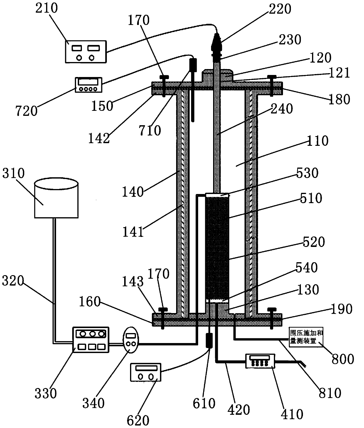
[0036] Please check figure 1 , a preferred embodiment of the ultrasonically controlled soil column pressure chamber system, the ultrasonically controlled soil column pressure chamber system includes a pressure chamber, a soil column, an ultrasonic device, a liquid supply device, a liquid outlet device, and a vibration measuring device , a temperature measuring device and a confining pressure applying and measuring device 800 .

[0037] A pressure chamber, which has a cavity 110 filled with water.

[0038] In this embodiment, the pressure chamber includes a cylindrical body 140, a top cover 150, and a bottom cover 160. The surrounding wall of the body 140 is a hollow double-layer structure, and a nano-based insulating soft felt 141 is provided. The hot soft felt 141 is attached to the peripheral wall of the body 140; the top of the body 140 is provided with an upper edge 142, the bottom of the body 140 is provided with a lower edge 143, and the top cover 150 is connected betwe...


PUM

PropertyMeasurementUnit
thicknessaaaaaaaaaa
pore sizeaaaaaaaaaa
radiusaaaaaaaaaa

Abstract

The invention discloses an ultrasonic control earth pillar pressure chamber system. The ultrasonic control earth pillar pressure chamber system comprises a pressure chamber, an earth pillar, an ultrasonic device, a liquid supply device and a liquid outlet device. The pressure chamber is provided with a cavity filled with water, and the earth pillar is arranged inside the cavity; the ultrasonic device comprises an ultrasonic generator, an ultrasonic transducer, an ultrasonic amplitude-change pole and an ultrasonic emission tool head, and the ultrasonic emission tool head extends into the cavity and makes contact with the top end of the earth pillar; the liquid supply device comprises a liquid inlet pipe, a liquid storage tank, a peristaltic pump and a flowmeter; the liquid outlet device comprises a turbidimeter and a liquid outlet pipe, the turbidimeter is connected to the liquid outlet pipe, and the liquid outlet pipe extends into the cavity and is connected with the bottom end of the earth pillar. The system can accurately measure the evolution situation of rubber concentration along with time, the ultrasonic attenuation situation, the temperature change situation and the earth pillar deformation situation in the process of ultrasonic load changes, earth pillar height changes and earth pillar confining pressure changes, and then research on rubber migration and deposition characteristic in porous media under the multi-factor coupling action is carried out.

Description

technical field [0001] The invention relates to an ultrasonic-controlled soil column pressure chamber system in environmental geotechnical engineering, which is used to measure colloid migration and deposition characteristics in porous media under the conditions of changing ultrasonic load, confining pressure and soil column height. Background technique [0002] With the rapid development of my country's economy and society, groundwater pollution is becoming more and more serious, which has a serious impact on the life and production activities of our residents. The structure of the underground aquifer is complex, the velocity of the groundwater is slow, and the pollution of the groundwater is difficult to detect and treat. Colloids such as oxides, clay particles, and humus present in the underground environment make the aqueous medium change from a two-phase medium (a fixed solid phase and a moving gas or liquid phase) to a three-phase medium, and the added term is the movi...

Claims


Application Information

Patent Timeline
Patent Type & Authority Applications(China)
IPC IPC(8): G01N15/08G01N29/22
Inventor 陈星欣蔡奇鹏张大山
Owner HUAQIAO UNIVERSITY
Learn More