Expansive soil tunnel supporting structure and method

A support structure and expansive soil technology, applied in tunnels, tunnel linings, earthwork drilling and mining, etc., can solve problems such as expansion, contraction, deformation, damage, etc., to prevent excessive grouting pressure, low economic cost, and reduce water and mud gushing The effect of the risk

Active Publication Date: 2017-09-26
中铁二十四局集团安徽工程有限公司 +1
View PDF9 Cites 7 Cited by
  • Summary
  • Abstract
  • Description
  • Claims
  • Application Information

AI Technical Summary

Problems solved by technology

[0004] Aiming at the above-mentioned defects of the prior art, the present invention provides an expansive soil tunnel support structure and method, which mainly prevents the deformation and collapse of the tunnel surface caused by excessive grouting pressure through the grout stop wall, and solves the problem of expansive soil tunnel support. Problems of expansion, contraction, deformation and failure due to mechanical properties of expansive soils

Method used


Image

  • Expansive soil tunnel supporting structure and method
  • Expansive soil tunnel supporting structure and method
  • Expansive soil tunnel supporting structure and method

Examples


Embodiment 1

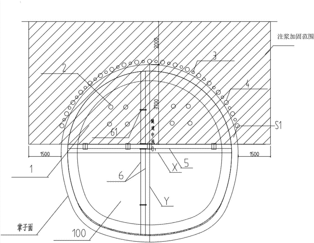
[0038] figure 1 Shown is the expansive soil tunnel support structure of the present invention, which includes:

[0039] A grout stop wall 1, which is arranged on the upper half-section S1 of the tunnel face of the expansive soil tunnel 100;

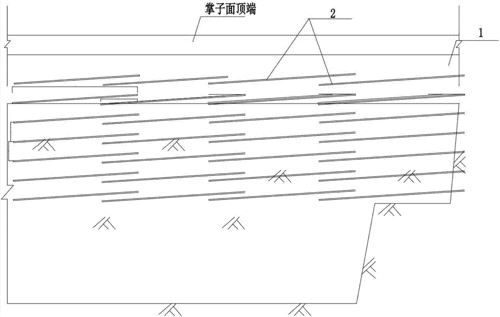
[0040] A plurality of grouting pipes 2, which are pre-embedded in the grout-stop wall 1, are used for advanced grouting of the expansive soil surrounding rock around the upper half-section S1 of the face of the expansive soil tunnel 100 to form a grouting Reinforcement range (in this embodiment, the size of the grouting reinforcement range is 1-1.5m extending outward from both sides of the tunnel surface, and 1.5-2m upwards from the top of the tunnel surface, i.e. figure 1 The rectangular area shown in the oblique box); the grouting pipes 2 are all arranged along the extension direction of the expansive soil tunnel 100 (that is, the direction perpendicular to the paper surface), and the cross-sections are all facing the tunnel face. Upp...

Embodiment 2

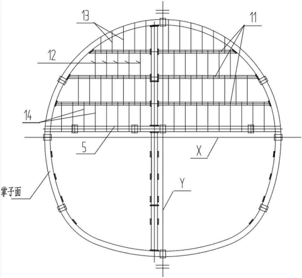
[0063] Such as Figure 5-6 Shown, the present invention also shows a kind of expansive soil tunnel support method, and it comprises the steps:

[0064] S1. Install a grout stop wall 1 on the upper half section S1 of the tunnel face of the expansive soil tunnel 100;

[0065] S2. A plurality of grouting boreholes 21 are drilled in the grout stop wall 1, and expansive soil surrounding the upper half section of the expansive soil tunnel 100 is embedded in each of the grouting boreholes 21. Grouting pipes 2 for advanced grouting; the grouting pipes 2 are arranged along the extension direction of the expansive soil tunnel, and the cross-sections are all facing the upper half-section S1 of the tunnel face;

[0066] S3. Perform advanced grouting through the grouting pipe 2 .

[0067] Preferably, before the step S1, the method further includes: S1a, setting an advance support structure.

[0068] Specifically, the step S3 includes:

[0069] S31. Configure the grouting material: In t...


PUM


Abstract

The invention discloses an expansive soil tunnel supporting structure and method. The expansive soil tunnel supporting structure comprises a wall for grouting and a plurality of grouting pipes, wherein the wall for grouting is disposed on an upper half section of a tunnel face of an expansive soil tunnel; and the grouting pipes are embedded in the wall for grouting and are used for performing pre-grouting on expansive soil surrounding rock on the periphery of the upper half section of the expansive soil tunnel. The grouting pipes are arranged in the extending direction of the expansive soil tunnel, and the cross sections of the grouting pipes are towards the upper half section of the tunnel face. When the pre-grouting is performed through the grouting pipes, the wall for grouting is used for preventing slurry for grouting from flowing outwards to the tunnel face. According to the expansive soil tunnel supporting structure, deformation and collapse of the tunnel face caused by too high grouting pressure are avoided mainly through the wall for grouting, and problems of expansion and shrinkage deformation and damage to the expansive soil tunnel caused by mechanical property of expansive soil are solved.

Description

technical field [0001] The invention relates to the field of geotechnical engineering, in particular to an expansive soil tunnel support structure and method. Background technique [0002] Expansive soils are widely distributed in my country, such as Guangxi, Yunnan, Henan, Hubei, Sichuan, Shaanxi, Hebei, Anhui, Jiangsu and other places. The mineral composition of expansive soil is mainly montmorillonite, which is a kind of highly plastic clay with high bearing capacity in general. Extremely unstable. Because the soil has the properties of water absorption, water shrinkage and reciprocating deformation, its damage to the tunnel support structure cannot be underestimated, and the damage it constitutes is not easy to repair. For example, after the excavation of the expansive soil tunnel, due to the stress redistribution and the action of water, etc., the tunnel repeatedly swells with water and shrinks when it loses water, which causes the tunnel to be squeezed and displaced ...

Claims


Application Information

Patent Timeline
Patent Type & Authority Applications(China)
IPC IPC(8): E21D11/10E21D11/38
CPCE21D11/10E21D11/38Y02E10/20
Inventor 王辅圣刘鹤唐永利赵见王佩哲黄旭尹君
Owner 中铁二十四局集团安徽工程有限公司
Why Eureka
Try Eureka