Transmitting mechanism of recreational facilities

A technology for launching mechanisms and amusement facilities, applied to mechanical equipment, non-mechanical drive clutches, fluid-driven clutches, etc., can solve the problems of increasing the difficulty of maintenance, increasing the manufacturing cost of launching mechanisms, and inconvenient maintenance. The effect of fast movement and convenient maintenance

Inactive Publication Date: 2011-05-18
GUANGDONG JINMA ENTERTAINMENT CORP LTD
View PDF7 Cites 6 Cited by
  • Summary
  • Abstract
  • Description
  • Claims
  • Application Information

AI Technical Summary

Problems solved by technology

[0003] At present, there are various structures for the launch mechanism of amusement facilities. At present, one is realized by the hydraulic clutch structure. It has the characteristics of large driving force, relatively small and compact volume, but due to the need for strict sealing and The recycling of hydraulic oil increases the manufacturing cost of the launch mechanism; moreover, it is necessary to use an oil tank to cover the hydraulic clutch, connecting flanges and connectors, etc., and the cooling oil is thrown out of the clutch and then taken by the oil tank; and At the same time, the hydraulic clutch is also connected with the clutch shell by a flange, so that maintenance personnel cannot observe the internal working conditions of the clutch from the outside, especially the wear condition of the friction plate is difficult to grasp at the first time, which increases the difficulty of maintenance , resulting in inconvenient maintenance

Method used


Image

  • Transmitting mechanism of recreational facilities
  • Transmitting mechanism of recreational facilities
  • Transmitting mechanism of recreational facilities

Examples


Embodiment Construction

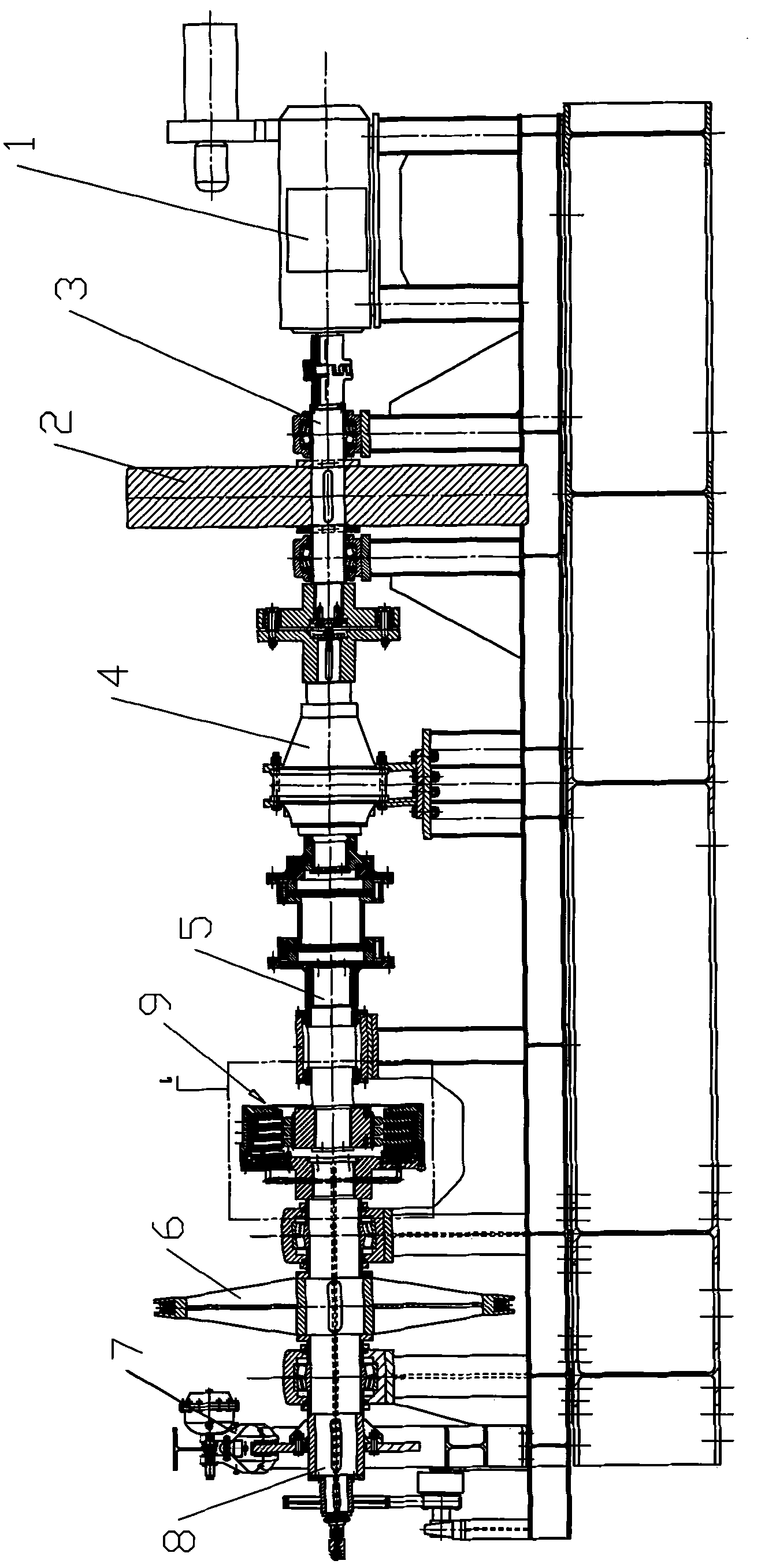
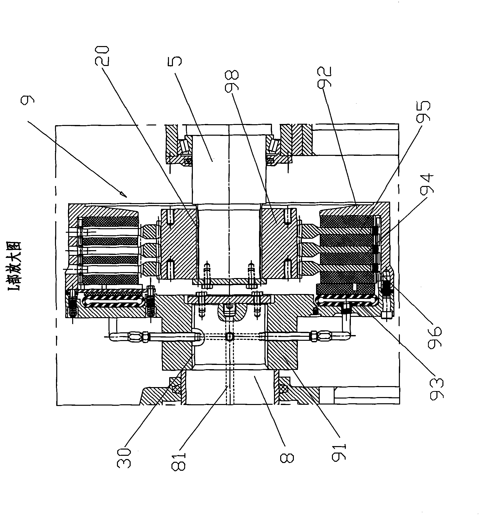
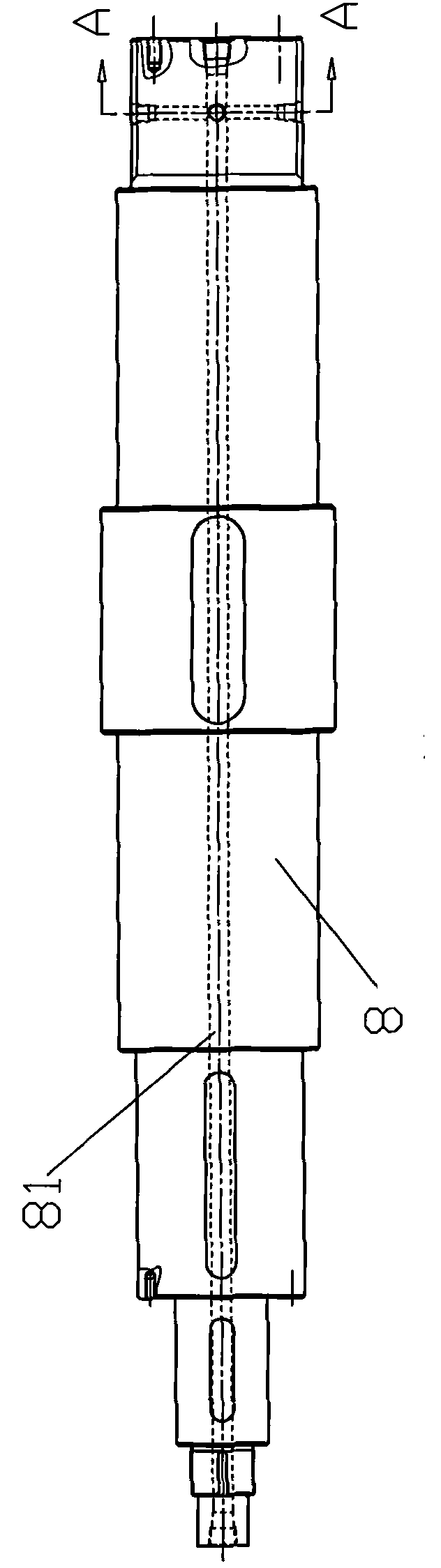
[0020] The present invention is a launching mechanism of an amusement facility including a flywheel shaft 3 with a flywheel 2 connected to the motor shaft of the driving motor 1, a speed reducer 4 arranged at the end of the flywheel shaft 3, and a speed reducer 4 connected to the output shaft of the speed reducer 4. The intermediate shaft 5, and the main shaft on which the driving sheave 6 and the brake 7 are arranged, wherein the driving sheave 6 is used as the final output power part of the launching mechanism to pull the ride of the amusement device to launch along the track, and The brake 7 is to stop the main shaft as soon as possible after the launching mechanism launches the ride-on device of the amusement device; a pneumatic clutch 9 is provided between the main shaft 8 and the intermediate shaft 5, and the pneumatic clutch 9 includes a The clutch driven seat 91 on the top and the clutch active seat 92 located on the intermediate shaft 5 constitute the clutch seat; a fr...


PUM


Abstract

The invention provides a transmitting mechanism of recreational facilities, comprising a flywheel shaft, a speed reducer, an immediate shaft and a main shaft, wherein the flywheel shaft is connected with a motor shaft of a driving motor and provided with a flywheel; the speed reducer is arranged at the end portion of the flywheel shaft; the immediate shaft is connected with the output shaft of the speed reducer and the main shaft is provided with a driving rope wheel and a brake; a pneumatic clutch is arranged between the main shaft and the immediate shaft; the pneumatic clutch comprises a clutch driven seat and a clutch driving seat, wherein the clutch driven seat is mounted on the main shaft and the clutch driving seat is disposed on the immediate shaft; a friction airbag is arranged in the clutch driven seat; a plurality of friction discs and fluted discs distributed at intervals in turn are arranged in the clutch driving seat from one side facing to the friction airbag; a stressed spring is arranged between the adjacent friction discs; the main shaft is provided with an air inlet passage whish is respectively communicated with the air supply device and the friction airbag in the axial direction; and the friction airbag is provided with a quick discharging valve capable of fast discharging high pressure gas therein to external. The transmitting mechanism is reasonable in structure, fast in starting and braking, low in production cost and convenient in maintenance.

Description

【Technical field】 [0001] The invention relates to an amusement facility, in particular to a launching device of the amusement facility. 【Background technique】 [0002] Amusement facilities ride on devices, such as motorcycle roller coasters, "jumping machines", etc., are all driven by the power of the launching mechanism, and continue to orbit under the action of inertia after launching to the set speed. favored by young people. The launching mechanism of the amusement facility refers to that it quickly pushes out the passenger device of the amusement facility to obtain a certain amount of kinetic energy, and then converts the kinetic energy into the potential energy of the passenger device, and then the passenger device slides freely by relying on the potential energy. [0003] At present, there are various structures for the launch mechanism of amusement facilities. At present, one is realized by the hydraulic clutch structure. It has the characteristics of large driving ...

Claims


Application Information

Patent Timeline
Patent Type & Authority Applications(China)
IPC IPC(8): F16H37/00F16D25/00
Inventor 王剑晖
Owner GUANGDONG JINMA ENTERTAINMENT CORP LTD
Why Eureka
Try Eureka