Upper end sealed fuel valve

A closed, gas-fired technology, applied to valve details, safety valves, balance valves, etc., can solve problems such as increased production processes, increased costs, and difficult installation, to ensure firmness and reliability, facilitate installation, and reduce costs Effect

Inactive Publication Date: 2011-05-18
沈琦杰
View PDF6 Cites 4 Cited by
  • Summary
  • Abstract
  • Description
  • Claims
  • Application Information

AI Technical Summary

Problems solved by technology

In addition, due to the installation of pull rods, sealing covers and other devices on the top of the upper shell, the length of the solenoid valve is increased. When installing the valve, because the user's installation pipe is usually very close to the wall, it is often difficult to install. The method of installing the shell and then reinstalling the shell is also very common when installing the valve. The solenoid valve has not been tested after disassembly and assembly on site, which is prone to leakage and lead to safety accidents
Punching holes on the static iron core also means that the production process increases and the cost increases

Method used


Image

  • Upper end sealed fuel valve
  • Upper end sealed fuel valve

Examples


Embodiment Construction

[0014] Below in conjunction with accompanying drawing, the present invention is described in detail.

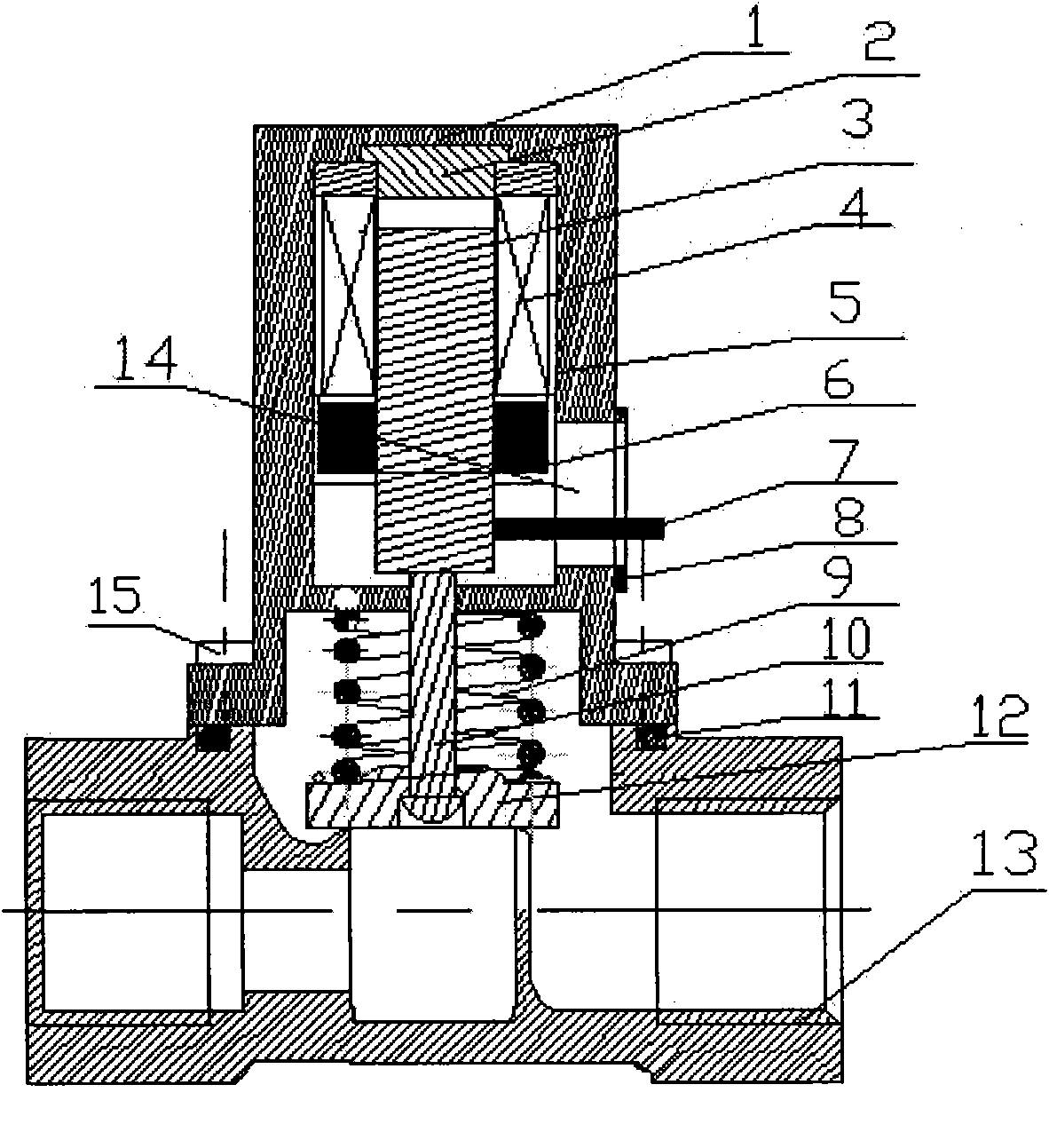
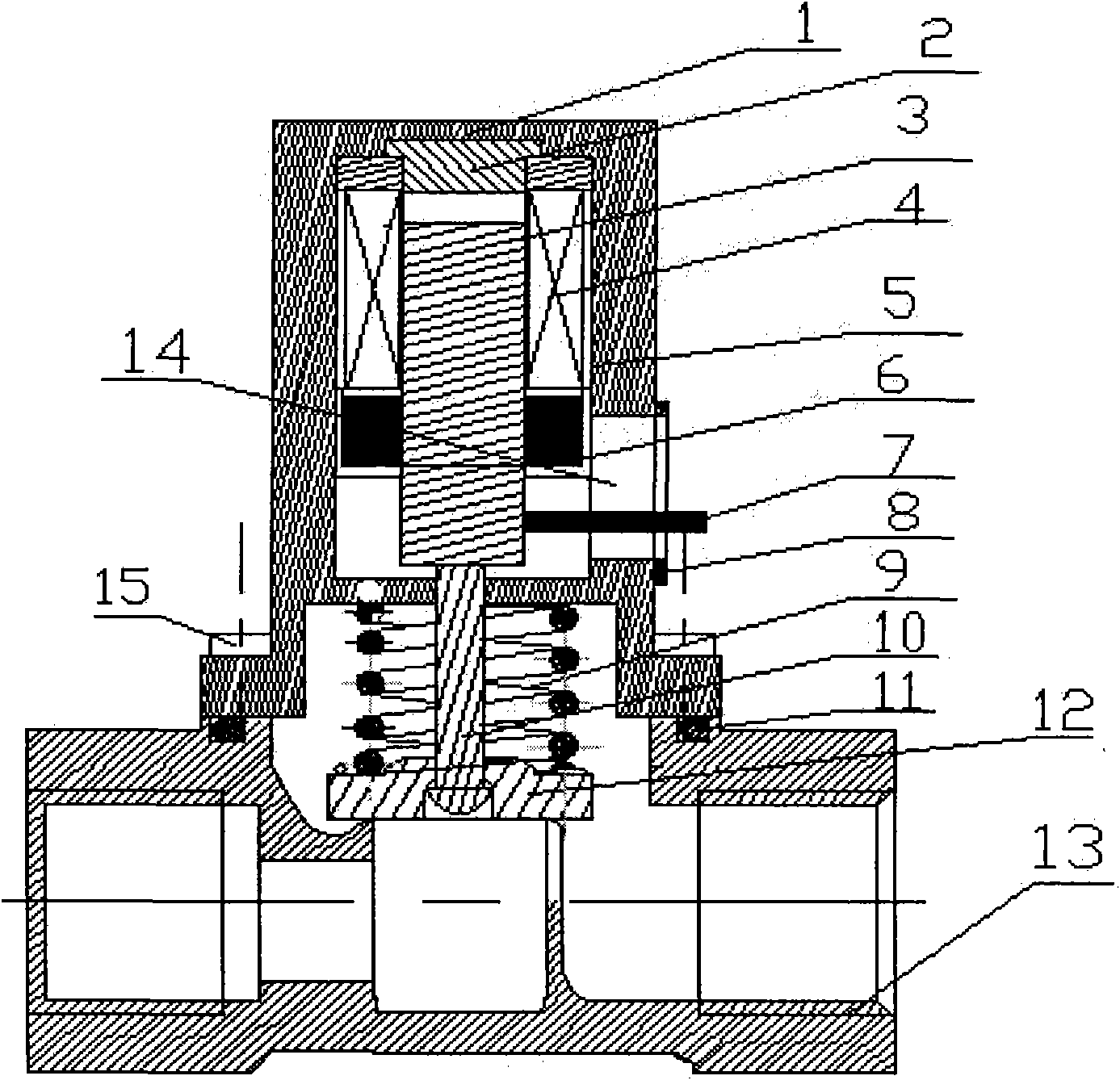
[0015] Such as figure 1 , an upper-end closed gas valve, comprising an upper casing 1 with a closed top, a lower casing 13 sealingly connected to the upper casing 1 through a screw rod 15 and a sealing ring 11, and a vent hole is arranged in the lower casing 13. Characterized by:

[0016] Between the upper casing 1 and the lower casing 13, a partition made integrally with the upper casing 1 is provided;

[0017] A cavity is formed between the upper casing 1 and the partition, a static iron core 2 is fixed on the top of the cavity, a coil 4 with a magnet 6 is fixed below the static iron core 2, and a moving iron core 3 is installed in the coil 4. A pull rod 7 is fixed on the side wall of the moving iron core 3, and a guide groove 14 is vertically provided on the side wall of the upper casing 1. With sealing cap 8;

[0018] A pull-down rod 10 is fixed at the bottom of the m...


PUM


Abstract

The invention discloses an upper end sealed fuel valve which comprises a lower shell (13) connected with an upper shell (1) in a sealing manner, wherein the lower shell (13) is internally provided with a ventilating hole. The upper end sealed fuel valve is characterized in that a baffle plate is arranged between the upper shell (1) and the lower shell (13), the top of a cavity of the upper shell (1) is fixed with a static core (2), a coil (4) with a magnet (6) is fixed under the static core (2), a movable core (3) is arranged in the coil (4), a pull rod (7) is fixed on the side wall of the movable core (3), a guide groove (14) is arranged on the side wall of the upper shell (1) along the vertical direction; the pull rod (7) penetrates through the guide groove (14) and extends out of the upper shell (1); the guide groove (14) is provided with a sealing cap (8); the bottom of the movable core (3) is fixed with a lower pull rod (10), the lower pull rod (10) extends into the lower shell (13) after penetrating through the baffle plate, the bottom of the lower pull rod (10) is fixed with an end cover cap (12) matched with the ventilating hole; and a spring (9) is arranged between the end cover cap (12) and the baffle plate.

Description

1. Technical field [0001] The invention relates to an upper-end closed gas valve with a gas alarm automatic cut-off device. When the gas leaks, the gas alarm will alarm and automatically close the gas valve, and the gas channel will be cut off. After eliminating the leakage factor, open the gas valve, and the user can use the gas normally, thus ensuring the safety of the user's life and property. 2. Background technology [0002] Now the valves that are suitable for automatic cut-off of gas leakage alarm are mainly composed of upper shell, moving iron core, static iron core, U-shaped frame, coil, magnet, upper pull rod, spring, sealing cap, lower pull rod, end cap, lower shell, etc. composition. Its working principle is: when the pull rod of the gas valve is lifted upwards, the magnetic field generated by the magnet makes the attractive force of the moving iron core and the static iron core greater than the pulling force of the spring, the moving iron core and the static i...

Claims


Application Information

Patent Timeline
Patent Type & Authority Applications(China)
IPC IPC(8): F16K17/00F16K31/06
Inventor 沈琦杰
Owner 沈琦杰
Why Eureka
Try Eureka