Fatigue test device of rubber bearing

A fatigue test, rubber bearing technology, applied in the direction of mechanical bearing testing, etc., can solve the problem of low rigidity of the fixture

Active Publication Date: 2011-05-18
SAIC VOLKSWAGEN AUTOMOTIVE CO LTD
View PDF0 Cites 10 Cited by
  • Summary
  • Abstract
  • Description
  • Claims
  • Application Information

AI Technical Summary

Problems solved by technology

[0004] In view of the problem in the prior art that the rotating mandrel is too high from the ground to cause the overall rigidity of the fixture to be too small, the purpose of the present invention is to provide a fatigue test device for rubber bearings, which can improve the overall rigidity of the test device

Method used


Image

  • Fatigue test device of rubber bearing
  • Fatigue test device of rubber bearing
  • Fatigue test device of rubber bearing

Examples


Embodiment Construction

[0016] The technical solutions of the present invention will be further described below in conjunction with the accompanying drawings and embodiments.

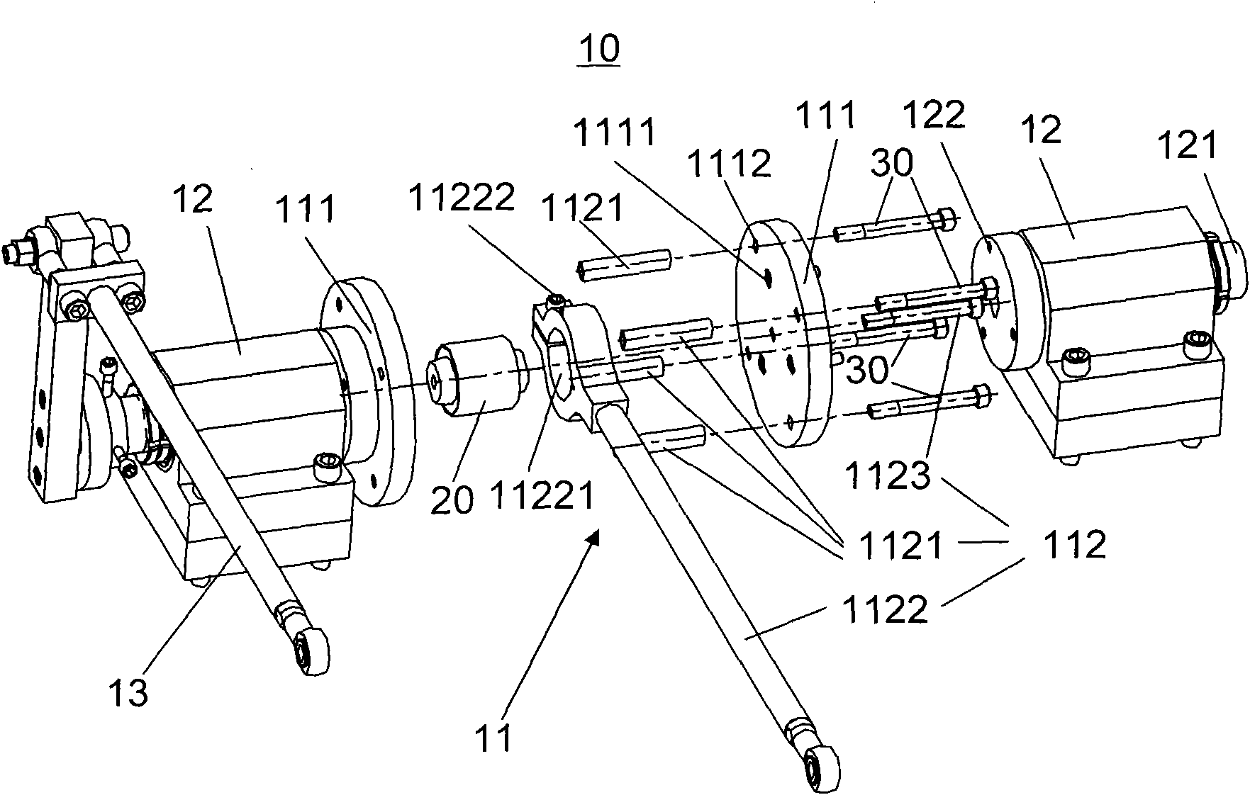
[0017] see image 3 , Figure 4 The fatigue test device 10 of the rubber bearing shown is set on the test platform of the test device, including a clamping mechanism 11, a pair of bearing seats 12 provided with a rotating mandrel 121, and a swing rod 13, and the bearing seats 12 are arranged symmetrically on the clamp. The two ends of tight mechanism 11, fork 13 are connected with the outer end of a bearing seat 12. The clamping mechanism 11 includes flanges 111 and fastening parts 112, the flanges 111 are respectively arranged on the inner ends of the bearing housing 12, and the fastening parts 112 are arranged between the flanges 111 and connected with the flanges 111 fixed. Since the flange is circular and the stiffness is isotropic, the rigidity of the clamping mechanism 11 in the direction of tension and pressure is al...


PUM


Abstract

The invention discloses a fatigue test device of a rubber bearing. The fatigue test device is arranged on a test platform and comprises a clamping mechanism, bearing seats and an oscillating bar, wherein the bearing seats are provided with rotary central spindles and are symmetrically arranged at the two ends of the clamping mechanism; and the oscillating bar is connected with the outer end of a bearing seat. Due the adoption of the bearing seat, the distance between the rotary central spindle of each bearing seat and the ground is lowered greatly, the rigidity of the entire fatigue test device is enhanced greatly, and situations such as the overall deformation of the fatigue test device under the action of single tensile pressure, easy breakage of the rotary central spindle due to long-time use and the like are avoided. The fatigue test device is convenient to use and maintain, and the using performance of the fatigue test device cannot be lowered and the service life of the fatigue test device cannot be shortened at a high temperature and a low temperature.

Description

technical field [0001] The invention relates to the field of fatigue detection of rubber bearings, in particular to a fatigue test device for rubber bearings. Background technique [0002] Rubber bearings are widely used as the main shock absorbing element in the chassis of automobiles. For example, rubber bearings are used at the joint between the sub-frame and the body, and rubber bearings are also used at the joint between the lower rocker arm and the sub-frame. However, because the internal colloidal structure of the rubber bearing is not uniform, the transmission of external loads to the rubber bearing will produce uneven stress distribution, and some of them are high stress concentration areas, which are often the weak points of the rubber bearing. Under the repeated action of external loads, cracks will first occur at the weak points. According to the characteristics of rubber, once cracks occur in the colloid, they will rapidly expand under the action of shear force ...

Claims


Application Information

Patent Timeline
Patent Type & Authority Applications(China)
IPC IPC(8): G01M13/04
Inventor 李文斌
Owner SAIC VOLKSWAGEN AUTOMOTIVE CO LTD
Why Eureka
Try Eureka