Anisotropism focusing large-dynamic stripe image converter

An anisotropic and large dynamic technology, applied in the field of large dynamic anisotropic focusing streak image tubes, can solve the problems of low gain and small dynamic range of streak image tubes, reduce the second-order aberration coefficient and improve the dynamic range. range, the effect of increasing spatial resolution

Active Publication Date: 2012-12-19
XI'AN INST OF OPTICS & FINE MECHANICS - CHINESE ACAD OF SCI
View PDF0 Cites 1 Cited by
  • Summary
  • Abstract
  • Description
  • Claims
  • Application Information

AI Technical Summary

Problems solved by technology

[0009] In order to solve the technical problems of low gain and small dynamic range of existing fringe image transformation tubes, the present invention provides an anisotropic large dynamic focusing fringe image transformation tube

Method used


Image

  • Anisotropism focusing large-dynamic stripe image converter
  • Anisotropism focusing large-dynamic stripe image converter
  • Anisotropism focusing large-dynamic stripe image converter

Examples


Embodiment Construction

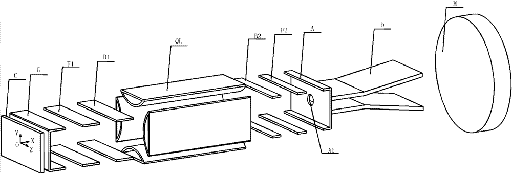
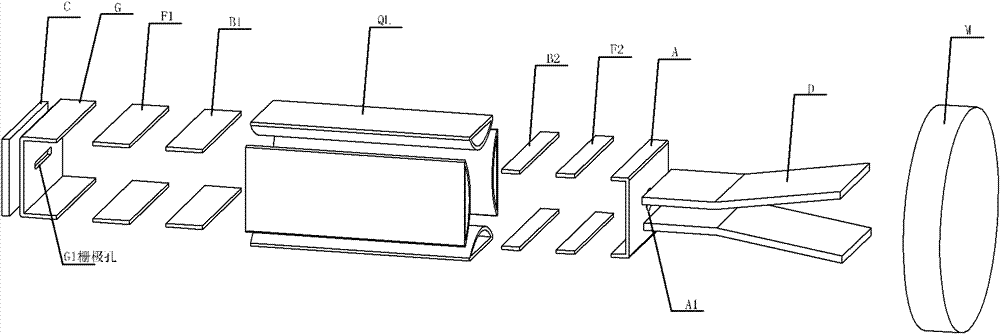
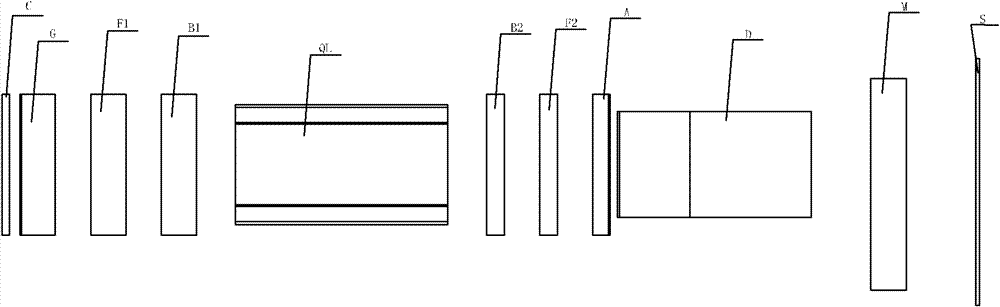
[0044] Such as Figure 1-9 As shown, the anisotropic focusing large dynamic stripe image transformation tube includes a photocathode C, (the grid G, the first time focusing electrode F1 and the first blanking electrode B1 together form a pre-time focusing system), an electric quadrupole focusing lens QL , the second blanking electrode B2, the second time focusing electrode F2, the anode A (where the second blanking electrode B2, the second time focusing electrode F2 and the anode A constitute the rear time focusing system), scanning deflector D, electron multiplier M, fluorescent screen S. The grid G ​​has a rectangular hole G1, the anode A has a rectangular circular hole A1 through which the electron beam B passes, and the photocathode C has a photoelectric conversion material.

[0045] The relatively separate structure of space focusing (electric quadrupole focusing lens) and time focusing is conducive to modulating the electron beam into a strip-shaped electron spot in the...


PUM


Abstract

The invention relates to an anisotropism focusing large-dynamic stripe image converter which comprises a photoelectric cathode, a pre-time focusing system, a space focusing system, a post-time focusing system, a scanning deflector, an electron multiplier and a fluorescent screen that are sequentially arranged in the transmitting direction of an electron beam, wherein the space focusing system is an electric quadrupole focusing lens; an anode hole for the electron beam to penetrate through is arranged on an anode, the photoelectric cathode is provided with a photoelectric transmitting material, a grid is provided with a rectangular grid hole for the electron beam to penetrate through; the photoelectric cathode is of a surface structure, the grid and the anode are rectangular grooves with three surfaces or five surfaces, and a first time focusing electrode, a first blanking electrode, a second blanking electrode and a second time focusing electrode are cylindrical lenses with rectangular frame structures or plate shaped electrode pair structures. The invention solves the technical problems of low gain and small dynamic range of the stripe image converter. According to the invention,the dynamic range of the stripe image converter is improved so that the electron beam realizes anisotropism focusing characteristics and the space charge effect is weakened.

Description

technical field [0001] The invention relates to a large dynamic anisotropic focusing fringe image transformation tube. Background technique [0002] Streak cameras are widely used in many cutting-edge scientific fields such as inertial confinement fusion (ICF), semiconductors, surface physics, photochemistry, photobiology, molecular research, plasma physics, ultrafast spectroscopy, X-ray lasers, etc. The recording of fast phenomena, the recently developed ultrafast electron diffraction technology has played a great role in promoting the development of ultrafast diagnostic technology. But it can reach 0.01 , so that the era of "molecular film or atomic film" that people dream of has come. The electronic pulse dispersed for a certain time basically arrives at the sample under test synchronously, and it is expected to achieve a time resolution of 100 fs. Nevertheless, the streak camera still plays an irreplaceable role, because the ultrafast electron diffractometer and the ...

Claims


Application Information

Patent Timeline
Patent Type & Authority Patents(China)
IPC IPC(8): H01J31/50H01J29/46H01J29/04H01J29/82
Inventor 田进寿徐向晏王俊锋曹希斌温文龙刘虎林邹玮董改云张铁王雅茹邹远鑫张小秋
Owner XI'AN INST OF OPTICS & FINE MECHANICS - CHINESE ACAD OF SCI
Why Eureka
Try Eureka