
Method for controlling mutual-control spare power automatic switching device based on two substations and three wires

A control method and self-switching technology, applied in circuit devices, electrical components, sustainable buildings, etc., can solve problems such as mis-switching, mis-operation, long communication path, and easy to be affected by interference sources, so as to avoid misoperation effect of behavior

Inactive Publication Date: 2011-05-18
YANGZHOU JIANGDU POWER SUPPLY COMPANY OF JIANGSU ELECTRIC POWER
View PDF0 Cites 14 Cited by
  • Summary
  • Abstract
  • Description
  • Claims
  • Application Information

AI Technical Summary

Problems solved by technology

However, due to the long communication path of this method, it is easily affected by interference sources in the signal transmission path, resulting in miscasting and misoperation.

Method used


Image

  • Method for controlling mutual-control spare power automatic switching device based on two substations and three wires
  • Method for controlling mutual-control spare power automatic switching device based on two substations and three wires
  • Method for controlling mutual-control spare power automatic switching device based on two substations and three wires

Examples


Embodiment Construction

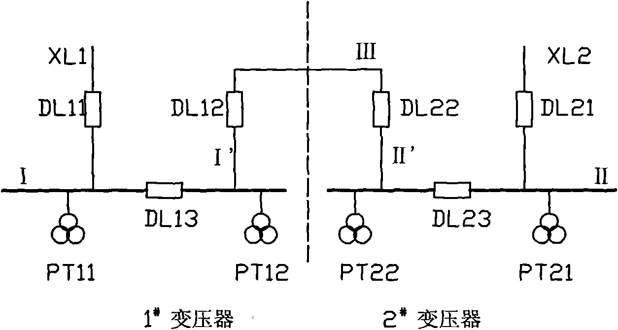
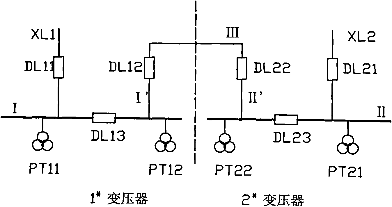
[0031] The present invention as figure 1 , 2 As shown, the mutual control equipment self-injection device includes 1 # transformer circuit, 2 # Transformer circuit, the busbar I and busbar II of the two transformers are connected through the busbar I', the connecting line III and the busbar II'; 1 # A circuit breaker DL11 is connected between XL1 of the transformer circuit and bus I, DL12 is provided on bus I', DL13 is provided on bus I between the above two circuit breakers, and PT11 and PT12 are respectively provided at both ends of bus I; 2 # The transformer circuit includes DL21, DL22, DL23, and PT21 and PT22, with 1 # The same wiring form as the transformer circuit, the 1 # transformer circuit, 2 # The transformer circuit is provided with a controller one and a controller two respectively; the controller one includes a control computer one, an electric terminal one and an optical terminal one, and the controller two includes a control computer two, an electric termin...


PUM


Abstract

The invention provides a method for controlling a mutual-control spare power automatic switching device based on two substations and three wires, relating to a control method of a spare power automatic switching device. Communication connection between two substations which are mutually spare is established, thus reducing or avoiding false switching and false tripping. The mutual-control spare automatic switching device comprises transformer circuits No. 1 and No. 2, buses I and II are connected by virtue of a bus I', an interconnection line III and a bus II'; the circuit No. 1 is also provided with a DL(Data Line)11, a DL13, a DL12, a PT(Power Transformer)11 and a PT12; the circuit No. 2 comprises a DL21, a DL22 and a DL23 as well as a PT21 and a PT22 and is the same as the circuit No. 1 in connection mode, and the transformer circuits No.1 and No. 2 are respectively provided with a controller 1 and a controller 2; the controller 1 comprises a control computer 1, an electric terminal machine 1 and an optical terminal machine 1, the controller 2 comprises a control computer 2, an electric terminal machine 2 and an optical terminal machine 2; the optical terminal machine 1 and the optical terminal machine 2 mutually communicate by virtue of optical fibers; the breaker and the voltage transformer of each transformer circuit are respectively connected with the control computer in the transformer circuit; and actions under multiple conditions are executed.

Description

technical field [0001] The invention relates to a control method of a backup power automatic input device, in particular to a control method applicable to a backup power automatic input device for two stations and three lines. Background technique [0002] According to the requirements for the reliability of the incoming power supply in the construction of medium and low voltage substations, generally medium and low voltage substations are designed with dual power supplies in mind. However, due to the limitations of urban corridors, the number of system distribution intervals, and investment funds, the situation where two substations are connected in series into "2 stations and 3 lines" (such as figure 1 ) often appear in medium and low voltage systems. Each of the two substations has a main incoming line, and the other is a shared connection line through which the two stations are connected together. This connection line is not a power line in the conventional sense. At th...

Claims


Application Information

Patent Timeline
IPC IPC(8): H02J9/06H02J13/00
CPCY02E60/723Y02B90/222Y04S20/12Y04S10/16Y02B90/20Y02E60/00
Inventor 虞旭顾进华伟王莉魏以宏
Owner YANGZHOU JIANGDU POWER SUPPLY COMPANY OF JIANGSU ELECTRIC POWER
Learn More