Injector

A technology for syringes and syringes, applied in the field of syringes, which can solve problems such as insufficient sterilization and difficulty in entering hydrogen peroxide gas, and achieve the effects of ensuring airtightness, functional reliability, and increased reliability

Active Publication Date: 2013-06-19
DENKA CO LTD +1
View PDF3 Cites 1 Cited by
  • Summary
  • Abstract
  • Description
  • Claims
  • Application Information

AI Technical Summary

Problems solved by technology

Therefore, it can be seen that for the area between the base end opening of the syringe and the above-mentioned flange part, although the hydrogen peroxide gas can easily enter the interior of the syringe from the gap between the base end opening of the syringe and the plunger rod cross section, However, the existence of the flange portion makes it difficult for hydrogen peroxide gas to enter the above-mentioned substantially airtight space closer to the front end than the flange portion.
When this happens, there is a possibility that the sterilization of the inner peripheral surface of the syringe or the outer peripheral surface of the plunger rod existing in the axial region from the above-mentioned piston to the flange part may be insufficient.

Method used


Image

  • Injector
  • Injector
  • Injector

Examples


Embodiment approach

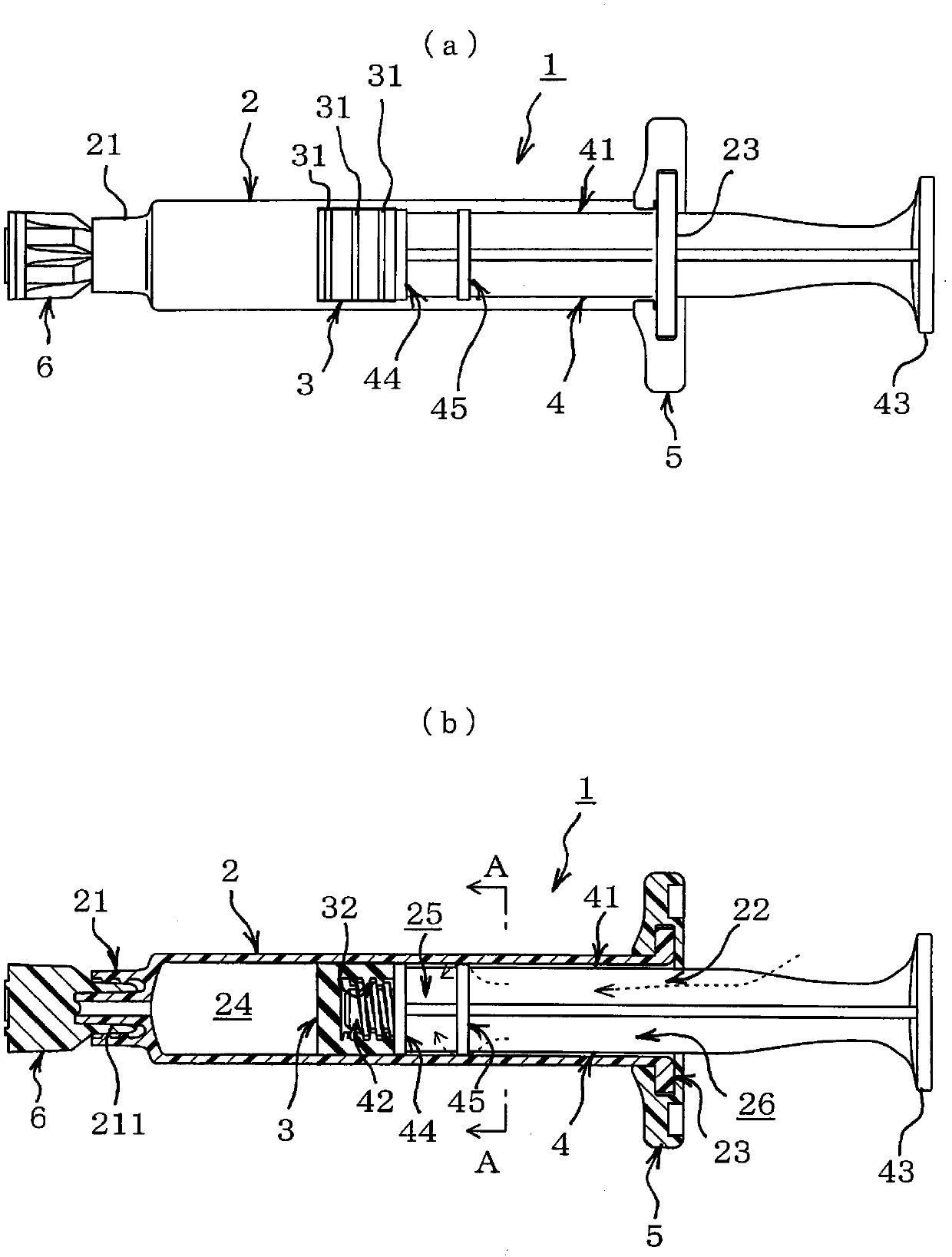
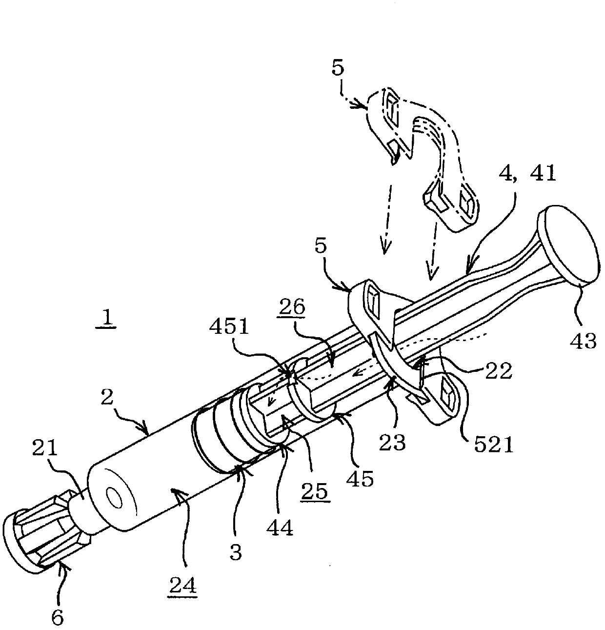
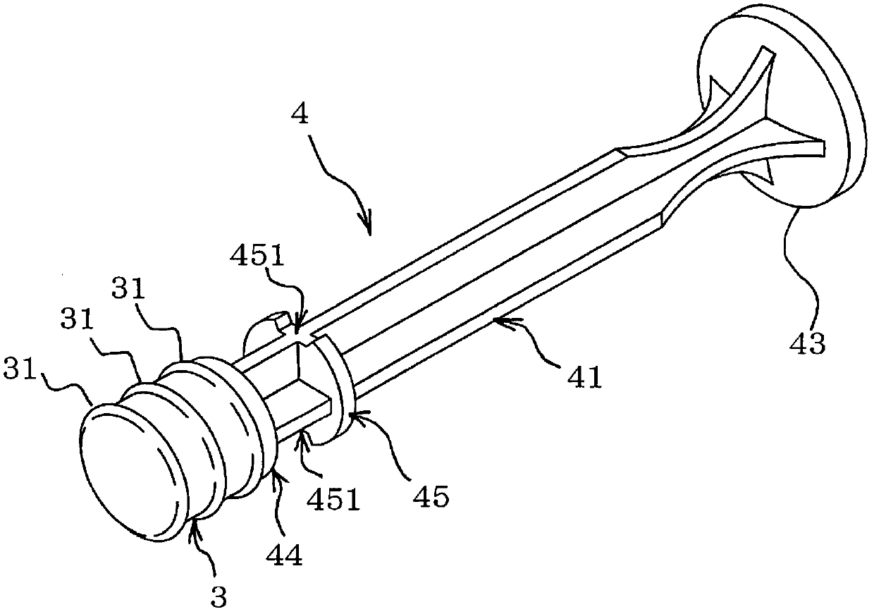
[0035] In addition, the present invention is not limited to the above-described embodiments, and includes other various embodiments. That is, in the above-mentioned embodiment, as the circulation opening formed on the disk portion 45, the following is shown: Figure 4 The groove-shaped communication openings 451, 451 shown, but as shown below, in the range that can fully ensure the circulation of the sterilizing gas and can ensure that the disc portion 45 and the hole edge 521 of the finger hook 5 stop each other, Various shapes, arrangements, and numbers of flow openings can be selected. For example, as the flow opening for ensuring the flow of sterilizing gas, it is possible to use Figure 4 The through hole shown in reference numeral 452, Figure 7 The slit-shaped communicating opening shown by reference numeral 453 in (a), Figure 7 The opening of the notch shown by reference numeral 454 in (b) or Figure 8 The cutting part indicated by the reference number 455 in.

...

Embodiment

[0040]Carry out the test of carrying out final sterilization step respectively with respect to embodiment and comparative example and confirm the bactericidal effect of embodiment and comparative example by comparison. As the final sterilization process, the prefilled syringe is placed in a sterilization tank filled with hydrogen peroxide gas in a state in which it is housed in the package, and sterilization is performed by contacting it with hydrogen peroxide gas. Examples are prefilled syringes using the plunger rod 4 with the communication opening 451 described in the above-mentioned embodiments, and Comparative Examples are prefilled syringes using the plunger rod without the communication opening 451 . Here, the opening area of ​​the communicating opening 451 in the embodiment is 1.1 mm. 2 .

[0041] In the sterilizing treatment of the final sterilizing process, the following packaging methods are used in the examples and the comparative examples. That is, a polyethylen...


PUM


Abstract

There is provided a injector in which a backstop function is realized by a collar part at a position situated away from a gasket in the direction of the side of the proximal end and adequate sterilization can be carried out, with a plunger rod (in which the collar part is formed) assembled, while aiming to secure airtightness. (A backstop function is realized by means of a collar part at a position situated away from the gasket in the direction of the side of the proximal end, thereby providing a injector capable of being adequately sterilized with a plunger rod (in which the collar part is formed) assembled, while aiming to secure airtightness.) A gasket (3) is inserted from a proximal end opening (22) of a barrel (2). Next, a plunger rod (4) is inserted as to establish connection of its distal end and the gasket (3). Then, a finger grip (5) is mounted to a flange (23). A disc part (45) is formed at a position situated away, in the direction of the side of the proximal end, from the gasket, thereby making it possible for the disc part (45) to abut and stop against an aperture edge (521) of the finger grip. There is formed in an outer peripheral edge part of the disc part (45) a communication opening part (451) having a concave shape. At the time of sterilization with hydrogen peroxide gas, the hydrogen peroxide gas which has flowed into an open space (26) from the proximal end opening is permitted to circulate in a semi-hermetically closed space (25) by way of the communication opening part.

Description

technical field [0001] The present invention is aimed at a syringe with a back stop function. In particular, the present invention relates to a syringe that can be favorably sterilized with a plunger rod inserted into a barrel and a back-stopper attached. The backstop function is a function for preventing the plunger from falling out of the barrel of the syringe. The function of the backward stopper is to form a flange on the plunger rod. On the other hand, after the plunger rod is inserted into the syringe, the backward stopper for stopping the flange is assembled in the syringe. On the base end side, even if the entire plunger rod is intended to be drawn out from the barrel, the flange portion abuts against the retraction stopper and cannot be drawn out. Background technique [0002] Conventionally, a sterilization treatment using hydrogen peroxide gas has been proposed as a sterilization treatment for a drug solution-filled syringe (pre-filled syringe) filled with a dru...

Claims


Application Information

Patent Timeline
Patent Type & Authority Patents(China)
IPC IPC(8): A61M5/31A61M5/28A61M5/315
CPCA61M2005/3104A61M2005/3139A61M5/31505A61M2005/31508A61M5/001
Inventor 满野彻宫田喜明日置和利多幡恒太星加博光松本一平朝日德彦
Owner DENKA CO LTD
Why Eureka
Try Eureka