Printer device

A technology of a printing device and a printing head, applied in the directions of printing devices, printing, typewriters, etc., can solve problems such as obstruction of the cutting unit 530, and achieve the effect of improving operability

Inactive Publication Date: 2011-05-18
MIMAKI ENG
View PDF8 Cites 6 Cited by
  • Summary
  • Abstract
  • Description
  • Claims
  • Application Information

AI Technical Summary

Problems solved by technology

In response to this request, there are the following issues: Figure 13 In this case, for example, when the cutter unit 530 is located on the printing unit 520 side and the two units are on standby at the right edge of the guide rail 510, when the printing unit 520 is to be moved above the platen 540 to perform printing , the cutting unit 530 will become an obstacle

Method used


Image

  • Printer device
  • Printer device
  • Printer device

Examples


Embodiment 1

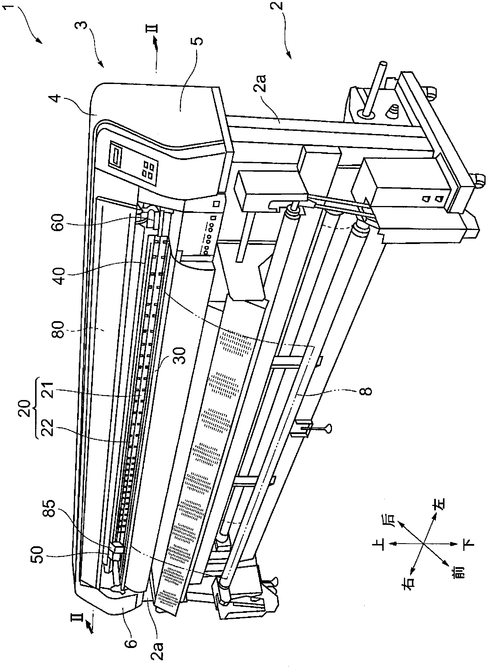
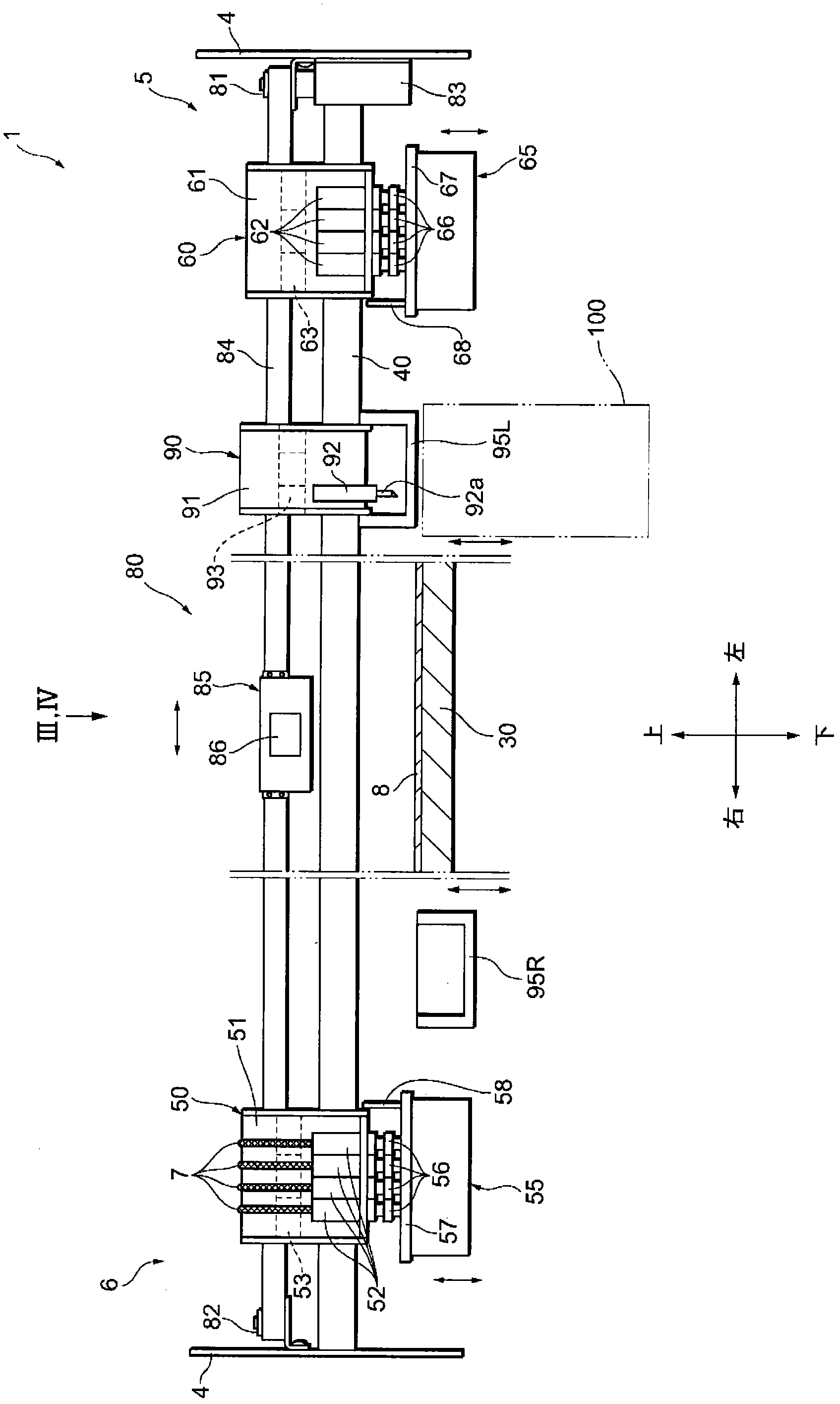
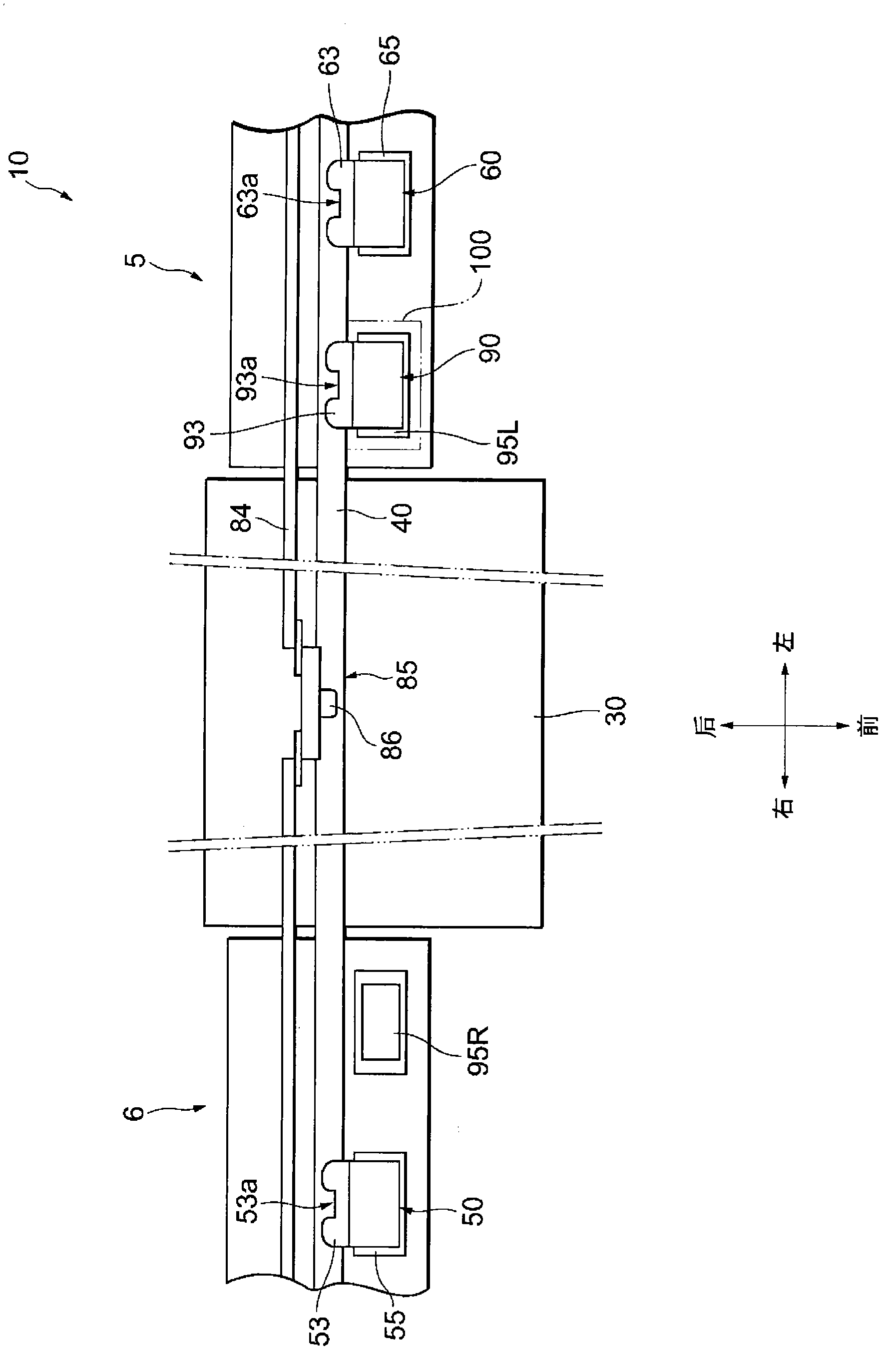
[0069] refer to Figure 1 to Figure 7 The configuration of the printing apparatus 1 of the first embodiment will be described. figure 1 shows a perspective view of the printing device 1, figure 2 and image 3 Indicates the vicinity of the guide rail 40 described later, Figure 4 It shows the plan view of the unit drive device 80 mentioned later, Figure 6 A cross-sectional view showing a connection portion between the drive carriage 85 and the connection portion 53 (the connection portion 63 and the connection portion 93 ), which will be described later, Figure 6 and Figure 7 The vertical movement mechanism 100 mentioned later is shown.

[0070] Such as figure 1 As shown, the printing device 1 is mainly composed of a main body 3 extending in the left-right direction, and a support part 2 for supporting the main body 3 and having a pair of left and right legs 2a, 2a. A left main body 5 and a right main body 6 are respectively formed on left and right ends of the main ...

Embodiment 2

[0098] Below, refer to Figure 8 and Figure 9 , the vertical movement mechanism 150 as another embodiment of the vertical movement mechanism 100 in the printing apparatus 1 of the first embodiment described above will be described. The same reference numerals are assigned to the members already described in the first embodiment above, and description thereof will be omitted. in addition, Figure 8 Indicates the state in which the cutting unit 90 is held by the left standby stage 95L, Figure 9 A state in which the cutting unit 90 moves downward and retreats is shown.

[0099] like Figure 8As shown, the vertical movement mechanism 150 is mainly composed of a vertical support member 151 connected to the left standby stage 95L and extending in the vertical direction, a left and right support member 152 connected to the bottom of the vertical support member 151 and extending in the left-right direction, A fixed support table 160 fixed to a frame member such as the leg 2 a o...

Embodiment 3

[0105] Below, refer to Figure 10 and Figure 11 The vertical movement mechanism 200 as another example of the vertical movement mechanism 100 of the printing apparatus 1 according to the first embodiment will be described. The same reference numerals are assigned to the members already described in the first embodiment above, and description thereof will be omitted. in addition, Figure 10 Indicates the state in which the cutting unit 90 is held by the left standby stage 95L, Figure 11 A state in which the cutting unit 90 has moved downward and retracted is shown.

[0106] like Figure 10 As shown, the up and down moving mechanism 200 is composed of an air cylinder 220 , the upper end of the cylinder rod 221 is installed on the left standby stage 95L, and the cylinder main body 222 is fixed in the fixed support platform 210 . According to this structure, in the state where the cutting unit 90 is held by moving the left standby stage 95L upward by the vertical movement m...


PUM


Abstract

The present invention provides a printer device. The printer device comprises a second printing unit, which has a carriage provided movably in a horizontal direction along a guide rail (40) and a printer head for discharging ink toward a printing sheet; a cutting unit (90), which has a carriage provided movably in a horizontal direction along a guide rail (40) and a cutter holder (92) for cutting the printing sheet into a predetermined shape; a second maintenance device which is capable of holding the second printing unit; a left standby station (95L) which is capable of holding the cutting unit (90); and a vertical movement mechanism (100) which is capable of integrally moving the cutting unit (90) and the left standby station (95L) up and down with respect to a platen (30). When performing printing while moving the printer head in the horizontal direction, the vertical movement mechanism (100) moves the cutting unit (90) and the left standby station (95L) to be positioned below the platen (30).

Description

technical field [0001] The present invention relates to a printing device that ejects ink from a printing head to perform predetermined printing on a printing medium. Background technique [0002] Such a printing device (inkjet printer) is configured to eject ink from nozzles formed on the lower surface of the printing head while causing the carriage on which the printing head is mounted to reciprocate relative to the printing medium, for example, in the left-right direction, and print on the printing medium. Implement the specified printing on the surface of the . Print heads for four colors, such as magenta (M), yellow (Y), cyan (C), and black (K) (hereinafter referred to as "basic colors"), are mounted on the carriage. , various colors can be expressed by making the ink ejected from these print heads adhere to the surface of the printing medium at a predetermined concentration. [0003] In recent years, a printing device has been developed in such a way that a cutting u...

Claims


Application Information

Patent Timeline
Patent Type & Authority Applications(China)
IPC IPC(8): B41J3/54
CPCB41J3/54B41J3/543B41J11/706B41J11/66
Inventor 池田明大西胜
Owner MIMAKI ENG
Why Eureka
Try Eureka