
Linear motion guide unit

a technology of motion guide unit and guide rod, which is applied in the direction of linear bearings, shafts and bearings, bearings, etc., can solve the problems of discrepancy between parts and troublesome assembly procedures, and achieve the effects of high precision, high precision and convenient fastening

Active Publication Date: 2017-07-25
NIPPON THOMPSON
View PDF8 Cites 1 Cited by
  • Summary
  • Abstract
  • Description
  • Claims
  • Application Information

AI Technical Summary

Benefits of technology

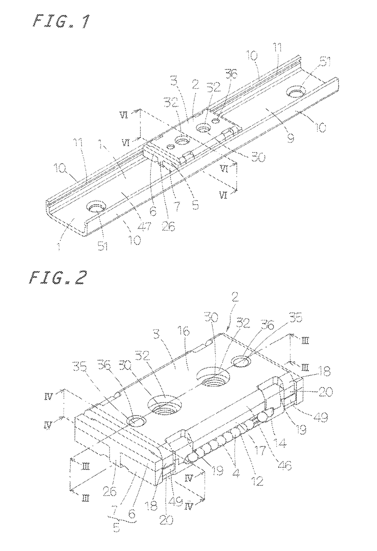
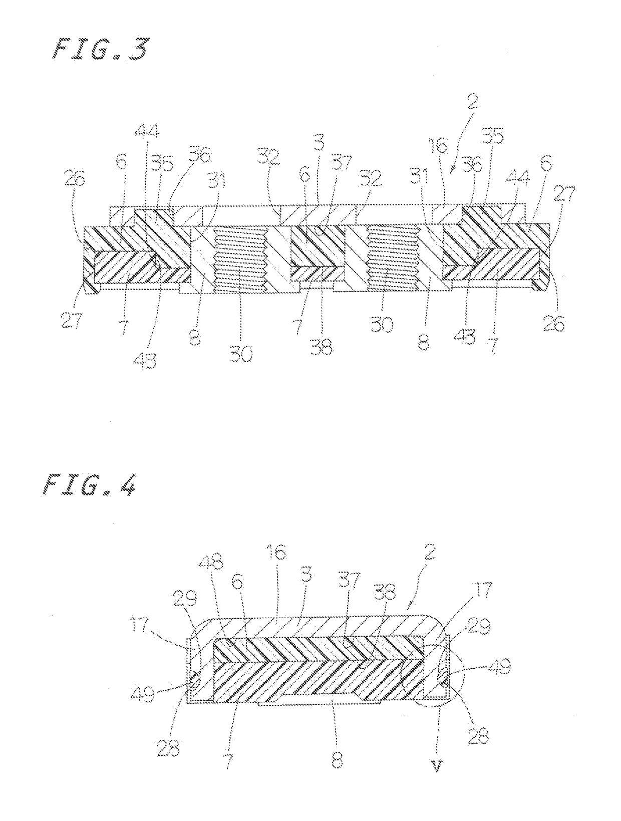
[0016]The mechanical strength of the linear motion guide unit is ensured by the carriage and the guide rail of stainless steal precisely formed in U-shape in transverse section. The slider is completed by the resiliently snap-fit assembly of the carriage and a pair of synthetic resin-made circulator halves having endless circulating circuits. Moreover, as the insert nuts are press-secured to the circulator of the slider, the counterparts such as works, instruments, and tools may be easily fastened by female mating with the insert nuts. With the linear motion guide unit of the present invention, furthermore, as there is no fear of integrated error in assembly of the slider, the assembly may be carried out easily with high precision. Moreover, the linear motion guide unit of the present invention makes it possible to carry out certainly with high precision locating among three members, that is, the carriage and two circulators. As a result, the slider is allowed to make smooth reciprocating movement relatively to the guide rail. Thus, the linear motion guide unit constructed as stated earlier is allowed to correspond smoothly with high precision to the sliding movement of the actuators and instruments. With the linear motion guide unit, moreover, the recess identical with the second raceway groove on transverse section is made to extend lengthwise on the extension of the second raceway groove outside the engaging part of the carriage and the recess fits over the convex wall surface of the hole of the circulator. Thus, as the recess serves as a provisional reference surface to locating the circulator relatively to the carriage, the carriage and the circulator are positioned easily with high precision. Accordingly, the circulator and the scooping part are easily located with accuracy. Then, the scooping part of the circulator and the second raceway groove of the carriage are located appropriately each other with accuracy so as not to cause any discrepancy between the scooping part and the second raceway groove, thereby allowing the rolling elements to roll with smooth through the circulating circuits to move the slider relatively with smooth along the guide rail. Though the carriage of the linear motion guide unit is made any thin steal plate, any counterparts such as instruments, tools and so on mounted on the carriage are fastened with female screws of the insert nuts press-fit into the circulators. Thus, the driving depth of the fastening screws of the slider is made deeper sufficient to fasten the counterparts with safety to the slider.

Problems solved by technology

This assembling procedure has had troublesome procedure.
Moreover, because the prior linear motion roll-bearing leaves any clearance between, for example any locating holes in the carriage and the locating pins of the circulator, any rattling caused among parts leads to any discrepancy between parts, especially any misalignment in location between the scooping part of the circulator and the raceway groove of the carriage.

Method used


Image

  • Linear motion guide unit
  • Linear motion guide unit
  • Linear motion guide unit

Examples


Embodiment Construction

[0049]The linear motion guide unit according to the present invention is adapted for use in any relatively sliding components in machinery as diverse as semiconductor fabricating equipment, various assembling machines, measurement / inspection instruments, medical machines, robotic machines, micromachines and so on to display the performance of smooth sliding movement and highly precision of the slider. Preferred embodiments of the linear motion guide unit constructed according to the present invention will be described in detail by reference to the drawings.

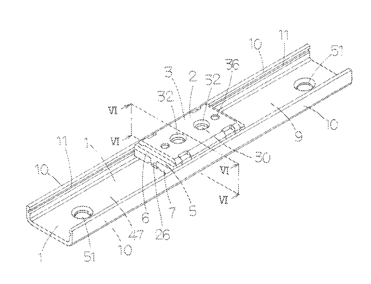
[0050]With the linear motion guide unit of the present invention, an elongated guide rail 1 is formed in a U-shaped configuration in cross-transverse section, which is composed of a pair of lengthwise side walls 10 (first side walls) and a lengthwise bottom 9 connecting the side walls with each other. A slider 2 fits mostly in a recess 47 defined between opposed lengthwise side walls 10 of the guide rail 1 so as to move or slide i...


PUM


Abstract

A slider is composed of four components except for rolling elements. A slider moving relatively to a guide rail is composed of a carriage having raceway grooves, a circulator to make a return passage and insert nuts to fit into through-holes in the circulator. Engaging parts of the carriage makes fit-engagement with holes in the circulator to make snap-fit between the carriage and the circulator to fasten them each other.

Description

FIELD OF THE INVENTION[0001]The present invention relates to a linear motion guide unit composed of a guide rail of U-shaped cross section having a raceway groove therein guide rail and a slider that fits over or conforms to the guide rail for linear movement relative to the guide rail.BACKGROUND OF THE INVENTION[0002]Modern linear motion guide units in recent years are demanded to perform high-precious tasks on reciprocating parts for a variety of instruments including in various reciprocating parts or components including semiconductor manufacturing machines, assembling machines, medical instruments, inspection and / or measurement devices. Members and / or parts for the linear motion guide units are required to make as integral as possible to decrease any errors and steps in assembly. Moreover, slider is desired to free of any working such as small holes, threaded holes and so on. The linear motion guide units may be indispensable machine elements for machines to guide linearly the s...

Claims


Application Information

Patent Timeline
Patent Type & Authority Patents(United States)
IPC IPC(8): F16C29/06F16C29/00
CPCF16C29/063F16C29/005F16C29/0602
Inventor NARA, TSUGUYOSHIKUWABARA, HIDEKI
Owner NIPPON THOMPSON
Learn More