
Linear actuator

A technology of linear actuators and actuating elements, applied in the direction of transmission, belts/chains/gears, mechanical equipment, etc., can solve expensive and difficult problems, and achieve simple and cheap solutions

Inactive Publication Date: 2011-05-18
LINAK AS
View PDF8 Cites 0 Cited by
  • Summary
  • Abstract
  • Description
  • Claims
  • Application Information

AI Technical Summary

Problems solved by technology

It's also hard and expensive

Method used


Image

  • Linear actuator
  • Linear actuator
  • Linear actuator

Examples


Embodiment Construction

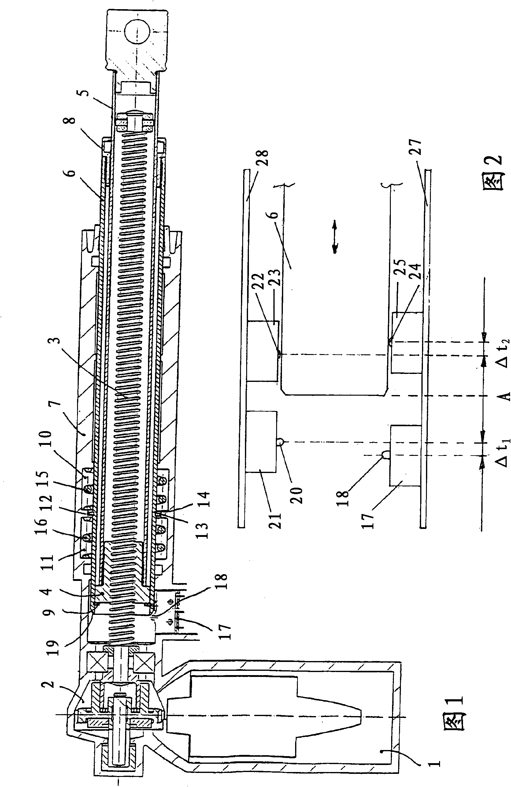
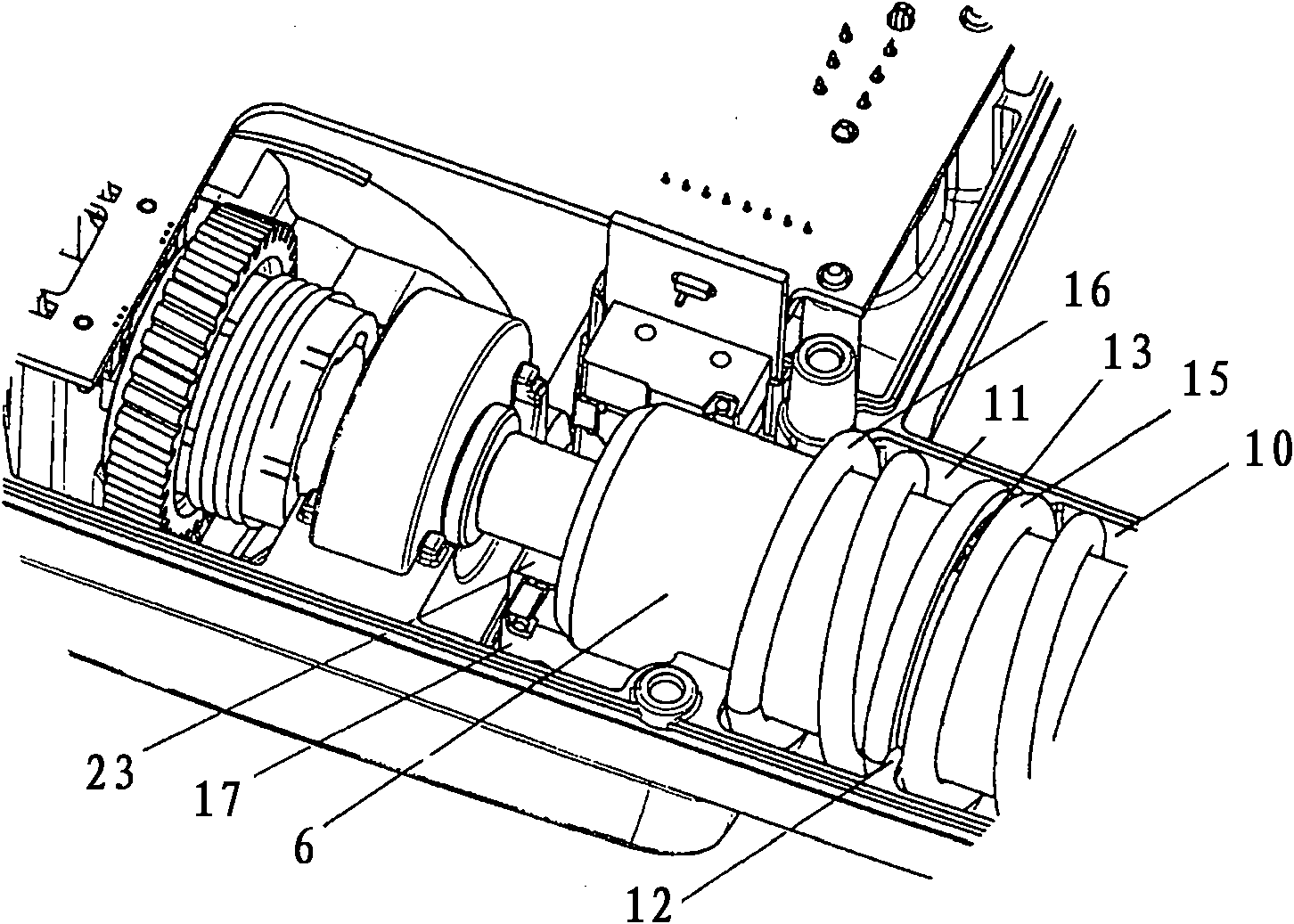
[0020] figure 1 A longitudinal section through a linear electric actuator is shown, basically comprising a DC low voltage electric motor 1 driving a spindle with a spindle nut 4 via a transmission 2 3. Mounted on the spindle nut 4 is a tubular shaped actuating element 5 equipped with a fixing at one end for mounting the actuator on the machine. When the fixture is mounted on the machine, the spindle nut 4 is fixed against rotation, so the spindle nut is moved outwards or inwards by the rotation of the spindle 3 depending on the direction of rotation of the spindle 3 . The spindle nut 4 and the actuating element 5 mounted on it are guided in a surrounding outer tube 6 which is equipped with a guide bush 8 at its free end. One end of the outer tube 6 is axially movably embedded in the housing 7 of the actuator. The outer tube 6 is internally equipped with a retaining ring 9 at its end protruding into the housing 7 . When the spindle nut 4 encounters the ring 9 during its run...


PUM


Abstract

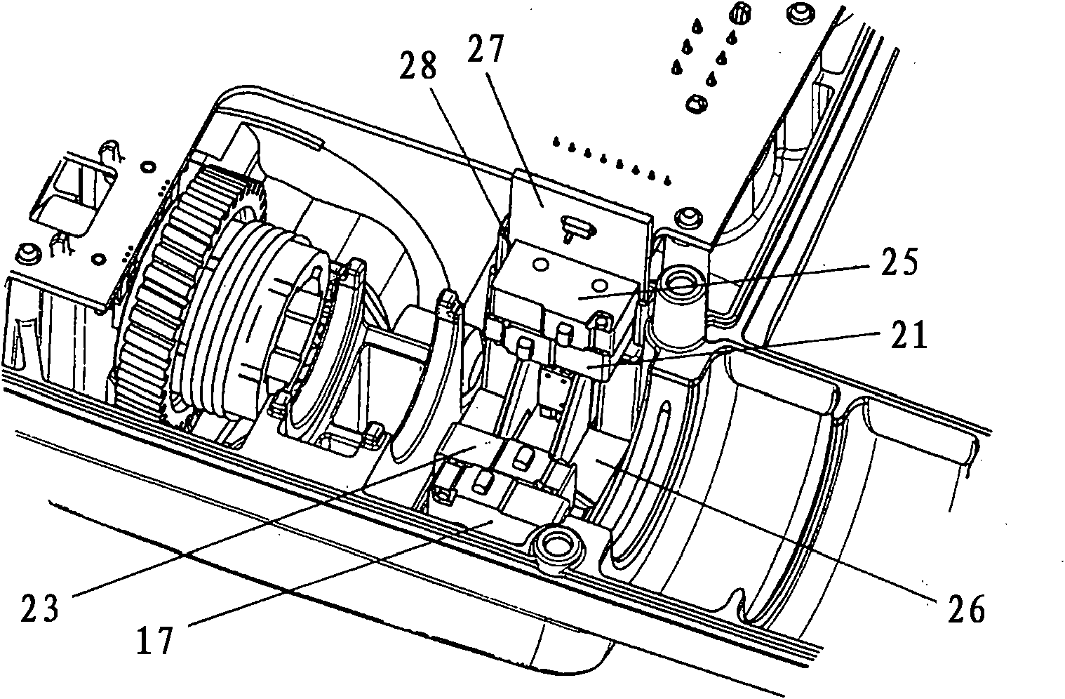
A linear electro-mechanical actuator comprises a housing with a reversible DC-motor (1), which through a transmission (2) can move an activation element (5) between two end positions. The activation element (5) will in the two end positions cause the electrical end stop switches (17, 25) to be activated for interrupting the current for the DC motor (1) in the end positions of the activation element (5) for running the motor (1) in one direction. Parallel to the end stop switches (17, 25), an extra set of switches (21, 23) are incorporated for determining in which end position the activation element (5) is located.

Description

technical field [0001] The invention relates to a linear actuator according to the preamble of claim 1 . Background technique [0002] The description of the invention begins with an electromechanical linear actuator in which a spindle with a rotationally fixed spindle nut is driven by a reversible electric motor through a transmission. An actuating element in the shape of a piston-like tube is mounted on the spindle nut. Alternatively, the actuating element can be designed integrally with the spindle nut, see eg WO 96 / 12123 by Koch (Okin). The actuation element is movable between two end positions, namely a retracted position and an extended position, depending on the direction of rotation of the motor. In these two end positions, the actuator is stopped due to the actuation of the end stop switch by the actuating element, which sends a signal to the control device in order to interrupt the current to the motor of the actuator. Alternatively, the switch acts directly as ...

Claims


Application Information

Patent Timeline
Patent Type & Authority Applications(China)
IPC IPC(8): F16H25/20
CPCF16H2025/2084F16H25/2015Y10T74/18688
Inventor J·巴斯特赫姆
Owner LINAK AS
Learn More