Temperature control within disk drive testing systems

A disk drive, test slot technology, used in temperature control, non-electric variable control, control/regulation systems, etc., to solve problems such as disk drive safety effects

Inactive Publication Date: 2011-05-18
TERADYNE
View PDF10 Cites 1 Cited by
  • Summary
  • Abstract
  • Description
  • Claims
  • Application Information

AI Technical Summary

Problems solved by technology

The smallest temperature fluctuations in the test environment can have a serious impact on precise test conditions and disk drive safety

Method used


Image

  • Temperature control within disk drive testing systems
  • Temperature control within disk drive testing systems
  • Temperature control within disk drive testing systems

Examples


Embodiment Construction

[0175] System Overview

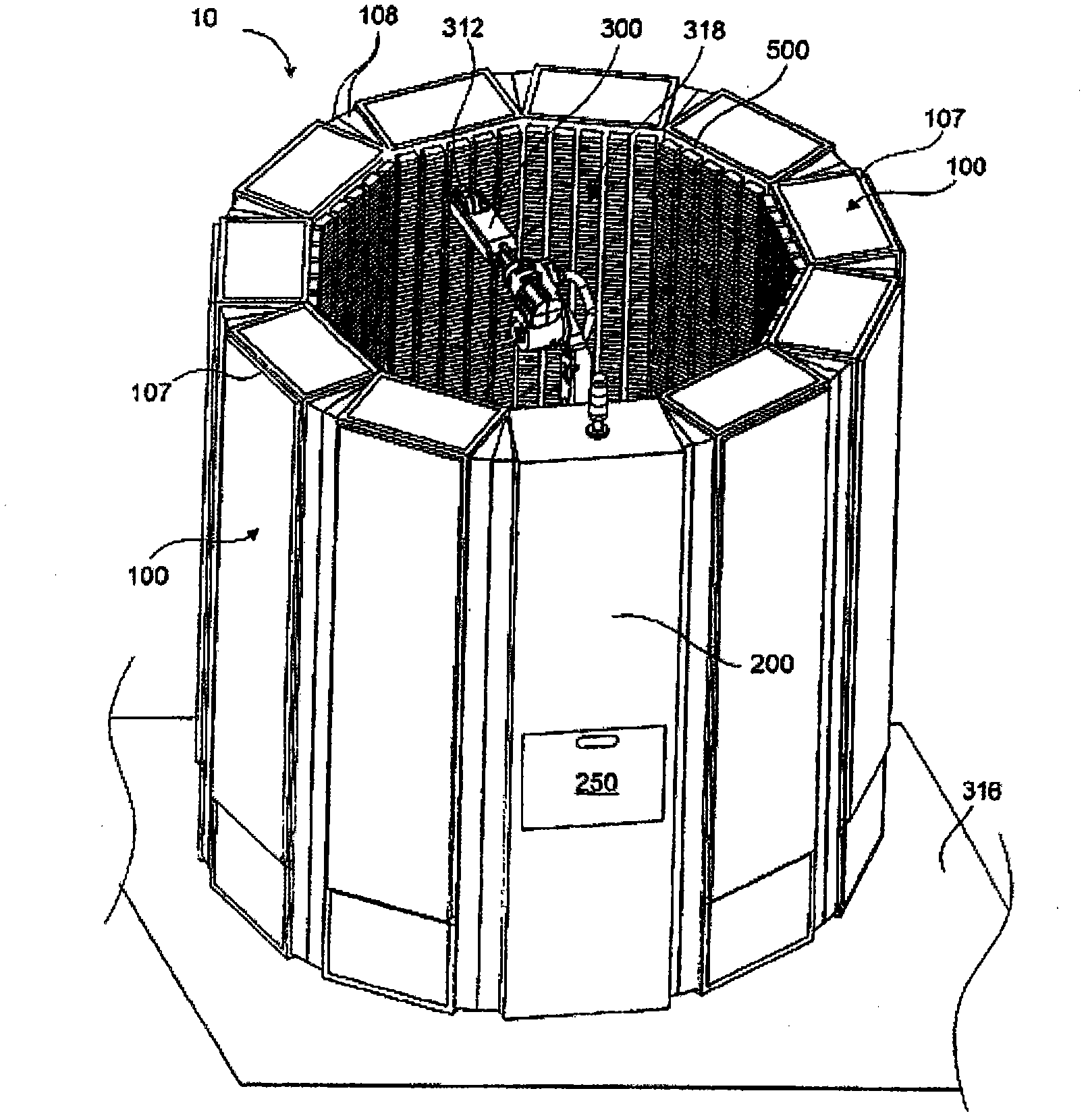
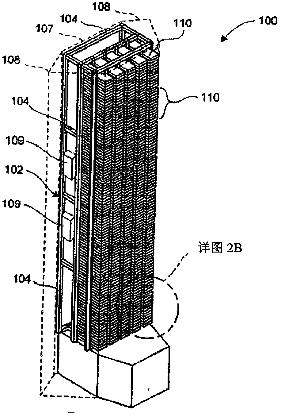
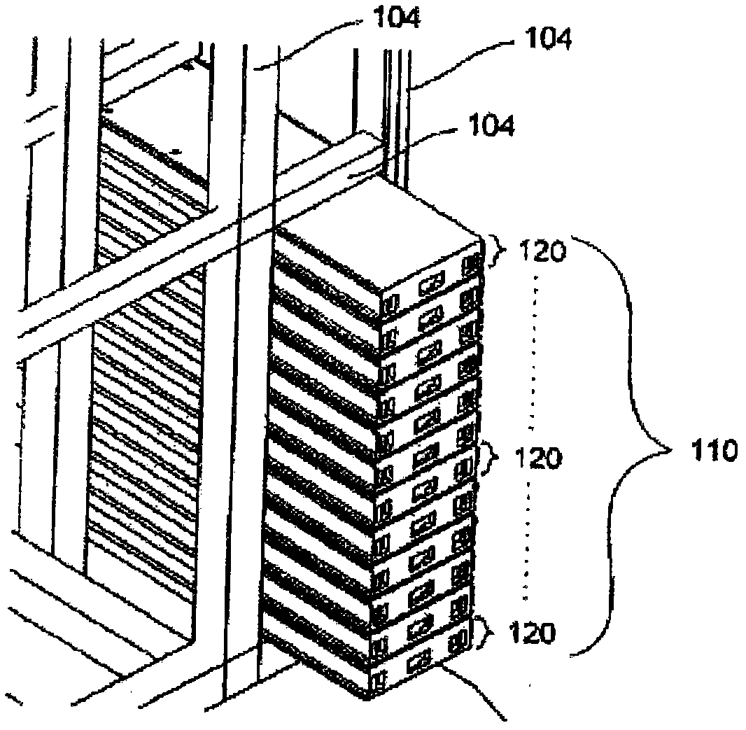
[0176] Such as figure 1 As shown, the disk drive testing system 10 includes a plurality of test racks 100 (eg, ten test racks are shown), a transfer station 200 , and a robot 300 . Such as Figure 2A and Figure 2B As shown, each test rack 100 generally includes a base 102 . The base 102 may be constructed from a plurality of structural members 104 (eg, aluminum extrusions, steel pipes, and / or assemblies) fastened together and together defining a plurality of socket sets 110 . Each socket set 110 can support a plurality of test socket assemblies 120 . refer to Figure 2A , the test stand 100 may also include a body 107 (e.g., formed from one or more sheet metal and / or molded plastic parts, see also figure 1 ), which at least partially seals the base 102. The body 107 can include a wedge portion 108 that can be used to separate power supply electronics 109 (eg, an AC to DC power supply). Such as image 3 As shown, each test slot assembly 120 ...


PUM


Abstract

A disk drive test slot thermal control system includes a test slot (500, 500a, 500b, 540). The test slot includes a housing (508, 550) and an air mover (722a, 722b) (e.g., a blower or a fan). The housing includes an outer surface (530, 559), and an internal cavity (517, 556). The internal cavity includes a test compartment (526, 560) for receiving and supporting a disk drive transporter (400) carrying a disk drive (600) for testing. The housing also includes an inlet aperture (528, 551) extending from the outer surface of the housing to the internal cavity. The air mover can be disposed outside of the internal cavity to provide an air flow towards the test compartment through the inlet aperture.

Description

technical field [0001] The present disclosure relates to regulating the temperature of a hard disk drive testing system. Background technique [0002] Disk drive manufacturers typically test the disk drives they produce to meet requirements. In order to test large numbers of disk drives connected in series or in parallel, test equipment and techniques are required. Manufacturers tend to test large numbers of disk drives simultaneously or in batches. A disk drive testing system typically includes one or more racks having a plurality of test slots for testing, the test slots housing the disk drives. [0003] During disk drive manufacture, the temperature of the disk drive is typically controlled, for example, to ensure disk drive functionality within a predetermined temperature range. To this end, the test environment in the immediate vicinity of the disk drives is finely tuned. The smallest temperature fluctuations in the test environment can have a serious impact on accu...

Claims


Application Information

Patent Timeline
Patent Type & Authority Applications(China)
IPC IPC(8): G05D23/00G11B20/18
CPCG11B33/128G11B33/144G11B33/1426
Inventor 布莱恩·S·梅洛
Owner TERADYNE
Why Eureka
Try Eureka