Safety landing device for high building

A technology for safe landing and high-rise buildings, applied in life-saving equipment, building rescue, etc., can solve problems that have not been reported before, and achieve the effect of low device cost, simple structure, and reduced landing cover area

Inactive Publication Date: 2011-05-25
张明德
View PDF0 Cites 1 Cited by
  • Summary
  • Abstract
  • Description
  • Claims
  • Application Information

AI Technical Summary

Problems solved by technology

After retrieving domestic and foreign patent documents and extensively consulting domestic and foreign publications, there is no report exactly the same as the technical solution of the present invention

Method used


Image

  • Safety landing device for high building
  • Safety landing device for high building

Examples


Embodiment 1

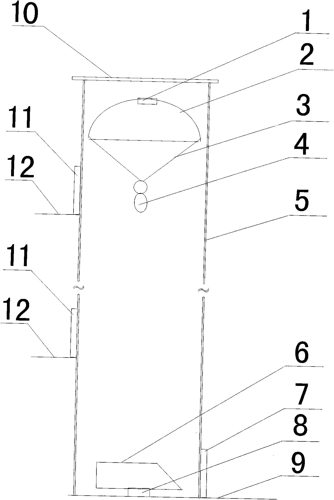
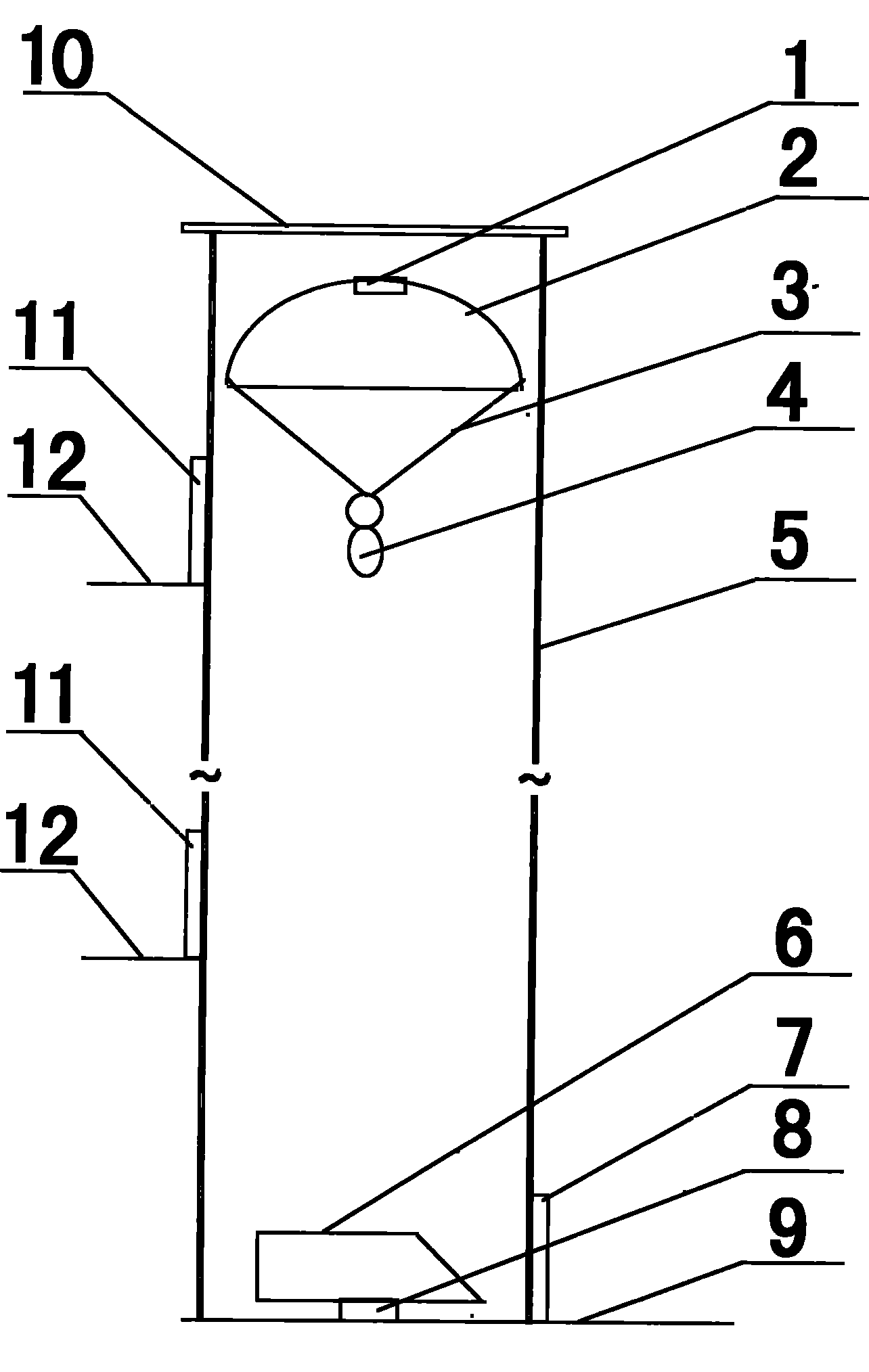
[0037] High-rise safety landing device, the landing cover 2 is made of an umbrella shape by 3 millimeters of thick hard plastic, and the lower part of the landing cover 2 is provided with 4 tethers 3 evenly distributed, and the descender 4 links to each other with the tethers 3. The top of the landing cover 2, is provided with a transom 1, and the landing person 4 uses a remote controller to control the closing and opening of the transom 1. The outside of the landing cover 2 and the tether 3 is provided with a protective tube 5, the protective tube 5 is made of cylindrical transparent plastic with a cross-sectional area of ​​2m 2 . The inner diameter of the protective tube 5 is greater than the outer diameter of the drop cover 2 by 10 millimeters. The bottom of the protection cylinder 5 is provided with a rectangular steel turntable 6 . One side of the turntable 6 is provided with a slope, which is convenient for people to slide down from the slope and go out from the exit d...

Embodiment 2

[0039] High-rise safety landing device, a hard ring is arranged on the bottom periphery of landing cover 2, and nylon cloth is made umbrella shape, is fixed on the hard ring. The outer diameter of the hard ring is 10 mm smaller than the inner diameter of the protective tube. The hard ring of the landing cover 2 is provided with 4 nylon tethers 3 evenly distributed, and the nylon tethers 3 are fixed on the 4 waists of the descender. The top of the landing cover 2 is provided with a transom 1, and the descender 4 uses a remote controller to control the closing and opening of the transom 1 to adjust the landing speed. The outside of the landing cover 2 and the tether 3 is provided with a protective cylinder 5, the protective cylinder 5 is made of cylindrical transparent plastic with a cross-sectional area of ​​3m 2 , the inner diameter is greater than the outer diameter of the drop cover 2 by 10 mm. The bottom of the protection cylinder 5 is provided with a rectangular steel tu...


PUM


Abstract

The invention belongs to high building fire self-rescuing technology, and discloses a safety landing device for high building. Fire self-rescuing escape is realized by sliding down from high altitude through apparatuses and ropes in the prior art, but the prior art has the defects that large space and floor are occupied when the ropes are obliquely arranged and persons with weak physical quality are unsafe during sliding down with the apparatuses. The exteriors of a landing cover (2) and a tied rope (3) are provided with a protective barrel (5), the protective barrel (5) is cylindrical, and the inside diameter of the protective barrel (5) is 6 to 16 millimeters more than the outside diameter of the landing cover (2); the lower part of the cylindrical protective barrel (5) is provided with a rotary table (6), and the lower part of the rotary table (6) is connected with a rotary shaft (8); and the lateral surface of the lower part of the protective barrel (5) is provided with an exit door (7), and the middle part of the protective barrel (5) is provided with an entrance door (11). The safety landing device has simple structure and low cost, can be used with buildings of various different heights, can be used for continuous landing of multiple persons, and has high utilization efficiency and landing safety.

Description

technical field [0001] The invention belongs to high-rise building fire self-rescue technology, in particular to a high-rise safety landing device. Background technique [0002] Fire self-rescue of high-rise buildings is a difficult technical problem that exists since high-rise buildings. With the development of society, the process of urbanization is accelerating, and urban land resources are in short supply. Buildings are built higher and higher, and more high-rise buildings continue to appear. High-rise buildings have improved the land utilization rate, but once a fire occurs, it will be difficult for people in the high-rise buildings to escape, causing huge loss of life and property. [0003] The prior art uses equipment and ropes to slide down from a high place to realize self-rescue escape in case of fire. This method is divided into two situations. The one is that the ropes are arranged obliquely, and people slide obliquely from a high place. However, the oblique ar...

Claims


Application Information

Patent Timeline
Patent Type & Authority Applications(China)
IPC IPC(8): A62B1/00
Inventor 张明德
Owner 张明德
Why Eureka
Try Eureka