Micropore drilling machining method of copper alloy and copper alloy parts
A processing method and copper alloy technology, which is applied in the field of micro-hole drilling, can solve the problems of affecting the accuracy of the drilling position, easy deviation of the drilling position, and many burrs at the exit, so as to improve the quality and efficiency of micro-hole processing And stable and reliable, reduce the effect of burrs
Active Publication Date: 2012-11-14
BEIJING INST OF CONTROL ENG
View PDF0 Cites 0 Cited by
- Summary
- Abstract
- Description
- Claims
- Application Information
AI Technical Summary
Problems solved by technology
[0005] ①Micro drill has small diameter, low rigidity, and extremely limited blade length. In order to avoid unnecessary length loss, precise tool setting is required
However, it is extremely easy to have a slight contact between the micro-drill and the workpiece during tool setting, which will cause the drill to break
[0006] ② Micro-drills have small diameter and low rigidity, and the drilling position is easy to shift, which seriously affects the accuracy of the drilling position, which in turn affects the size and shape accuracy of the micro-holes, and even directly causes the drill to break
[0007] ③ The diameter of the micro-drill is small, the chip space is very limited, and chip removal is difficult, resulting in chip clogging, increasing the heat and wear of the tool, reducing the service life of the tool or even breaking it
[0008] ④ The axial drilling force is relatively large, and there are many burrs at the exit, which are difficult to remove and easy to block the micropores
Method used
View moreImage
Smart ImageViewing Examples

Examples
Embodiment
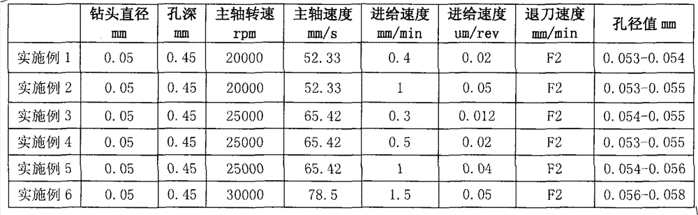
[0061] According to the above steps, use the Φ0.05mm micro-drill to process micro-holes on aluminum alloy parts with a thickness of 0.45mm. After the micro-drill is clamped, the radial runout error of the drill bit clamping part is less than 0.003mm. The implementation results are shown in the following table:
[0062]
[0063] It can be seen from the above table that for the Φ0.05mm micro-drill, the drilling process of micro-holes can be realized when the spindle speed is 20000rpm-30000rpm and the feed rate is in the range of 0.01μm / rev-0.05μm / rev.
Login to View More PUM
| Property | Measurement | Unit |
|---|---|---|
| diameter | aaaaa | aaaaa |
Abstract
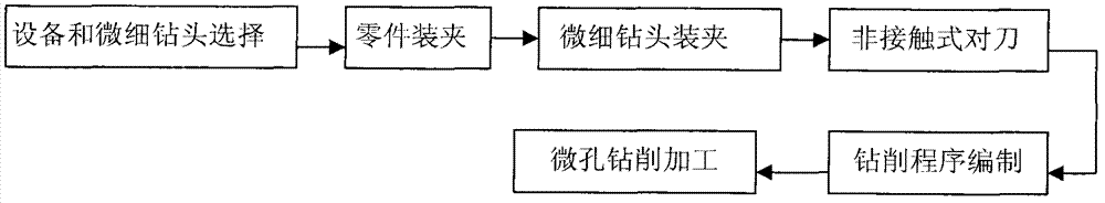
The invention provides a micropore drilling machining method of copper alloy and copper alloy parts. The micropore drilling machining method comprises the following steps: (1) selecting equipment and a superfine drill: (1.1) a selected numerical control machine meets the conditions that the rotation speed of a spindle is not less than 30000 revolutions per minute (rpm), the radial jump error of the spindle is not more than 0.003 mm, the positioning and re-positioning errors of a single shaft are not more than 0.005 mm, and a precise superfine drill clamping device is provided; and (1.2) the selected superfine drill meets the condition that the cylindricity of the superfine drill clamping part is less than 0.005 mm; (2) clamping the parts needing to be subjected to micropore machining on atool; (3) clamping the superfine drill, ensuring that the radial jump error of the superfine drill clamping part subjected to clamping is less than or equal to 0.006 mm; (4) carrying out non-contact type tool setting on the superfine drill and the parts; and (5) carrying out micropore drilling machining on the numerical control machine selected in the step (1), wherein the spindle speed of the numerical control machine is set between 50mm / s and 100mm / s, and the drilling feed speed of the numerical control machine is set between 0.01 mu m / rev and 1 mu m / rev.
Description
technical field [0001] The invention relates to a microhole drilling method, in particular to a microhole drilling method with a diameter below Φ0.1mm and a depth-to-diameter ratio greater than 8:1 on the planes and cylinders of aluminum alloy and copper alloy parts. Background technique [0002] The processing of micro-holes (hole diameter less than Φ0.5mm) with large depth-to-diameter ratio (greater than 8) is a worldwide processing problem. At present, the commonly used microhole processing mainly includes mechanical processing methods such as drilling, punching, and grinding, and special processing methods such as EDM, ultrasonic, laser, electrolysis, and electron beam processing. At present, in mechanical processing methods, because drilling microholes can achieve many advantages such as large depth-to-diameter ratio, high surface quality and high machining accuracy, drilling has always been the most widely used and most usable microhole machining. A strong method [1] ...
Claims
Login to View More Application Information
Patent Timeline
 Patent Type & Authority Patents(China)
IPC IPC(8): B23B35/00
Inventor 李兆光黎月明李利彭俊彬王建军孙慧丽张强
Owner BEIJING INST OF CONTROL ENG