Power hammer

A hammer and power technology, which is applied in the field of power hammer with clamping mechanism, can solve the problems that the components cannot be parallel to the center line of the casing, and the non-magnetic materials cannot be clamped, so as to achieve increased visibility and compact structure , The effect of shortening the sliding stroke

Inactive Publication Date: 2011-05-25
NANJING CHERVON IND
View PDF1 Cites 0 Cited by
  • Summary
  • Abstract
  • Description
  • Claims
  • Application Information

AI Technical Summary

Problems solved by technology

Its defects are: the magnet is on the edge of the casing, the nail cannot be placed in the center of the casing and the component is not parallel to the center line of the casing (that is, the nail is crooked after being absorbed), and it cannot clamp other non-magnetic materials, such as wood. Mortise, etc.

Method used


Image

  • Power hammer
  • Power hammer
  • Power hammer

Examples


Embodiment Construction

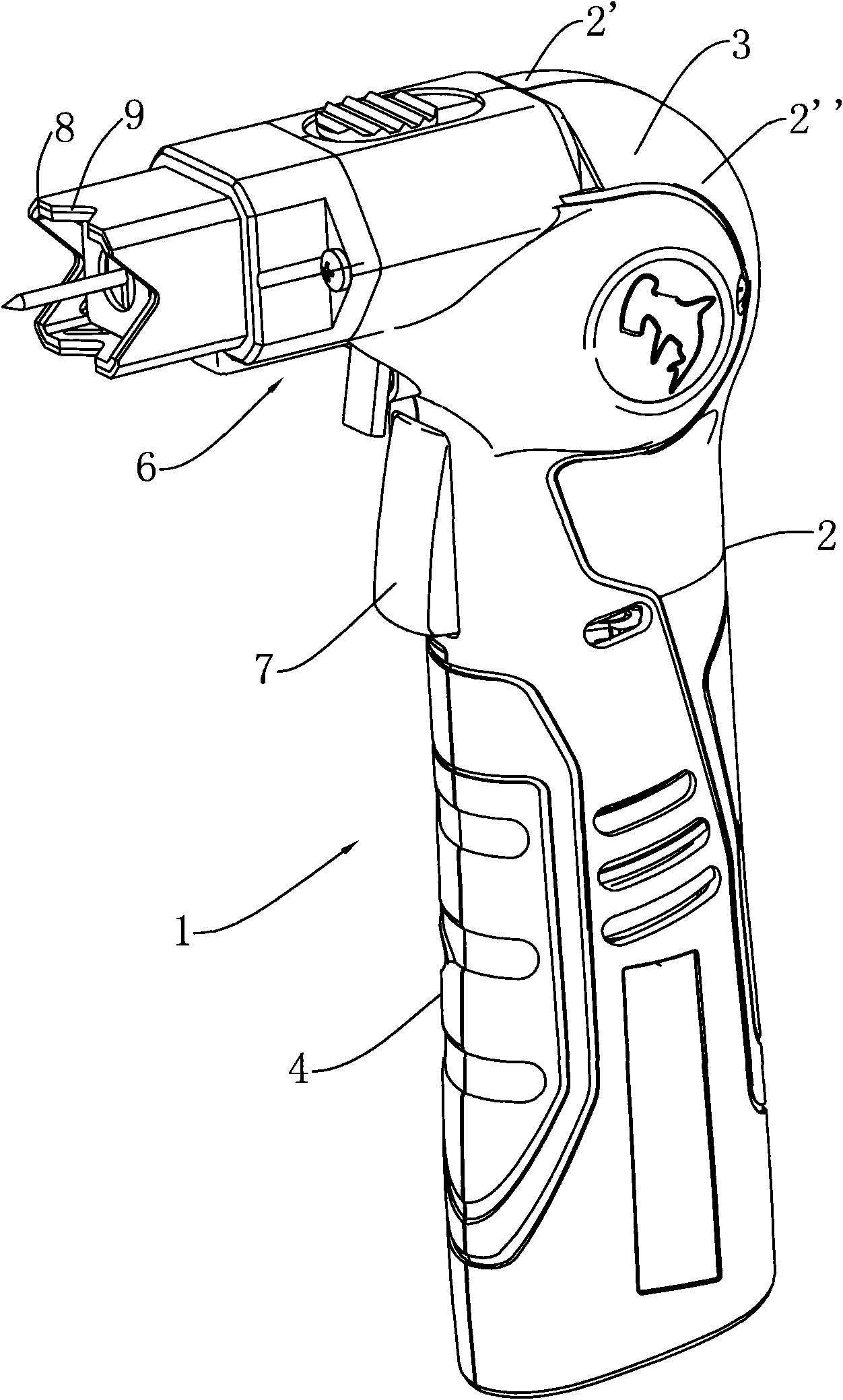
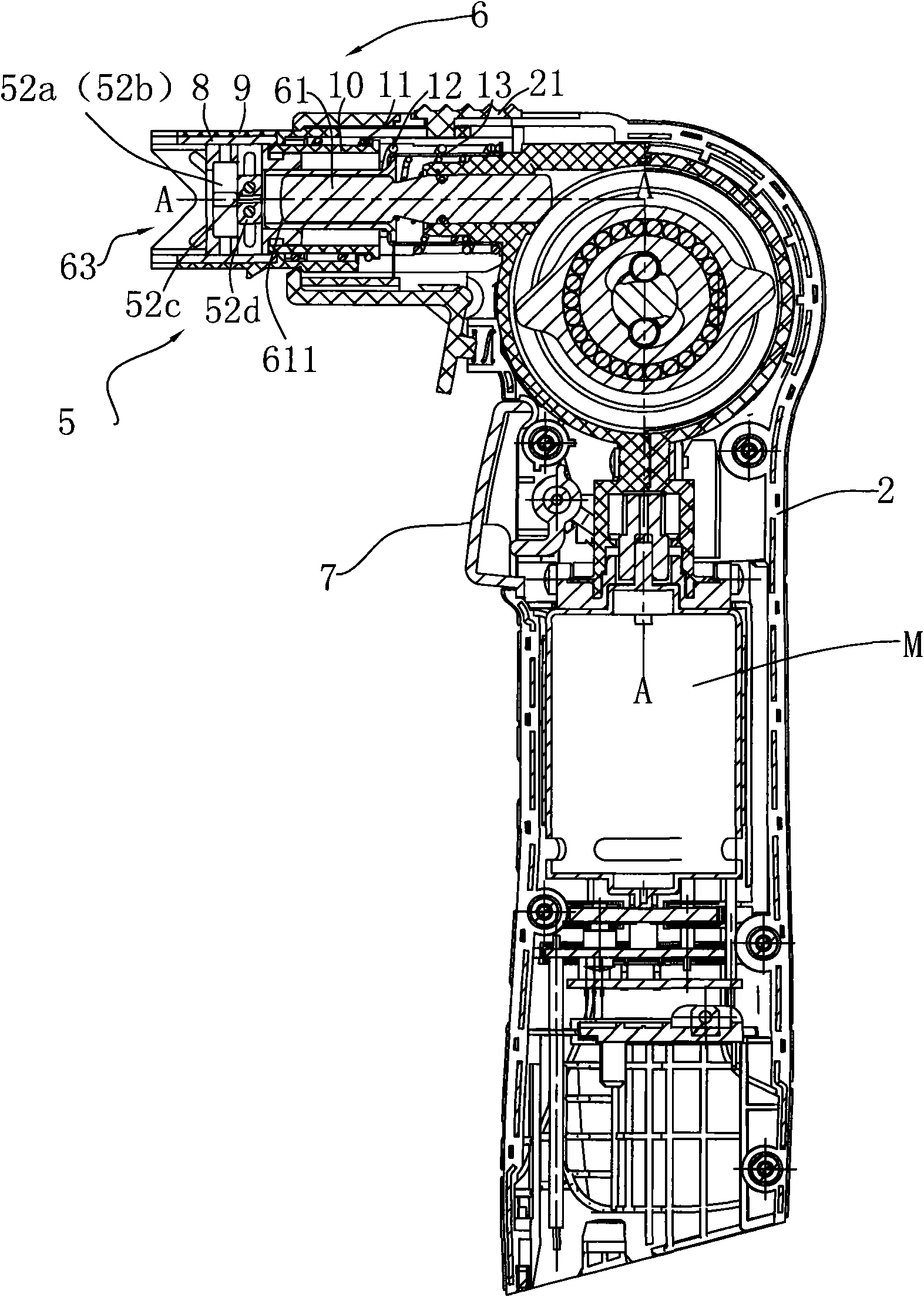
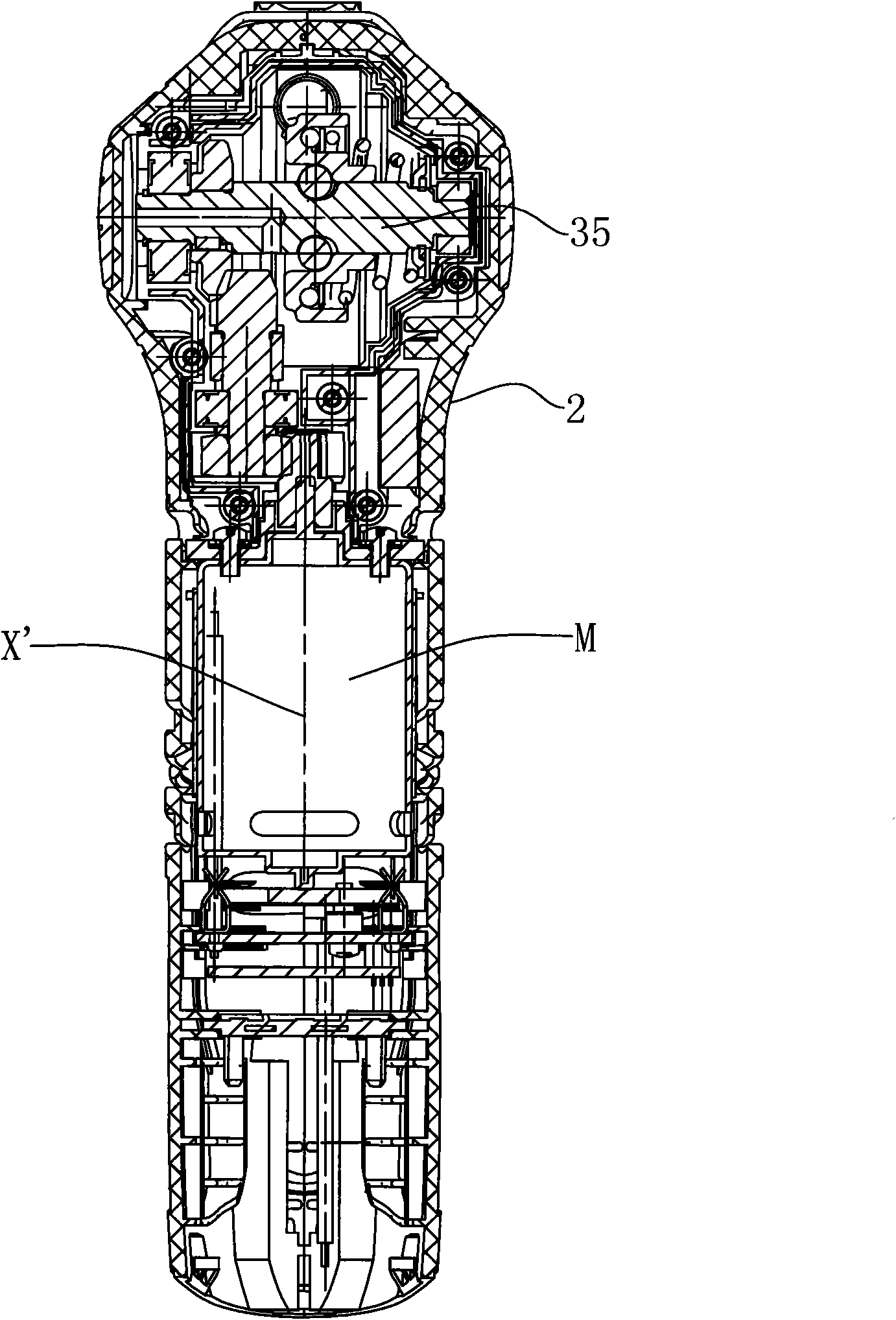
[0037] like figure 1 and figure 2 As shown, the power hammer 1 of this embodiment includes a casing 2 that accommodates the motor M and a striking device 6. The casing 2 is formed by combining left and right half casings 2' and 2". The main body of the casing 2 The part forms a substantially vertical gripping part 4, and the upper end contains a head assembly 3, which includes a transmission mechanism and a striking device 6 formed protruding forward.

[0038] In this embodiment, the power hammer 1 includes a battery pack (not shown) for powering the motor M. However, the power supply method of the power hammer disclosed in the present invention is not limited to this, and AC power can also be used for power supply. The switch 7 is installed on the casing 2 for controlling the start and stop of the motor M. The striking device 6 includes a striking member 61 which is substantially horizontal, is mounted in the striking device 6 by a spring, and can perform linear reciproca...


PUM


Abstract

The invention relates to a power hammer, which comprises a striking device. The striking device comprises a striking element and a clamping mechanism, wherein the striking element is used for repeatedly striking components; the clamping mechanism comprises a clamping element, a casing pipe, a first skewing device and a second skewing device; the casing pipe is provided with slots; the clamping element slides in the slots; the clamping element is closed relative to the first positions of the slots; the clamping element is opened relative to the second positions of the slots; the first skewing device is used for skewing the casing towards the direction of the striking element striking the components; the clamping mechanism also comprises a cutting ferrule; and the second skewing device is used for acting on the cutting ferrule towards the direction of the striking element striking the component to skew the clamping element. The power hammer has a compact structure, is convenient to operate and can be used for well clamping nails or other components so as to avoid that the nails or other components are struck to incline.

Description

[0001] This application is a divisional application of the Chinese application with the application number of 200910234451.0 and the filing date of November 19, 2009, with the title of "A Power Hammer". technical field [0002] The invention relates to a power hammer, in particular to a power hammer with a clamping mechanism. Background technique [0003] In the field of decoration and decoration, a power hammer is a relatively common tool, such as the power hammer disclosed in Chinese Patent Application No. 200820161342.1, which includes a body part and a gun nozzle part connected to the body. The muzzle part generally consists of a hollow cylindrical sleeve with a hole drilled into which a magnet can be placed, and the magnet engages in the hole to attract the nails placed in the striking device, thereby clamping the nails . Its defects are: the magnet is at the edge of the sleeve, the nail cannot be placed in the center of the sleeve and the element is not parallel to th...

Claims


Application Information

Patent Timeline
Patent Type & Authority Applications(China)
IPC IPC(8): B25D11/02B25D17/00
Inventor 周红陶
Owner NANJING CHERVON IND
Why Eureka
Try Eureka