
Kerf-improved tire used for automobile

A technology for cutting seams and automobiles, which is applied to road tires, tire parts, tire treads/tread patterns, etc., and can solve problems such as reduced cutting performance.

Inactive Publication Date:
View PDF7 Cites 5 Cited by
  • Summary
  • Abstract
  • Description
  • Claims
  • Application Information

AI Technical Summary

Problems solved by technology

However, in this case, if the tire wears out and the locking portion is exposed on the surface, the slit will disappear, and the performance of the slit will be greatly reduced.

Method used


Image

  • Kerf-improved tire used for automobile
  • Kerf-improved tire used for automobile

Examples


Embodiment Construction

[0012] Below, the present invention is described more specifically according to the accompanying drawings, and its content is as follows.

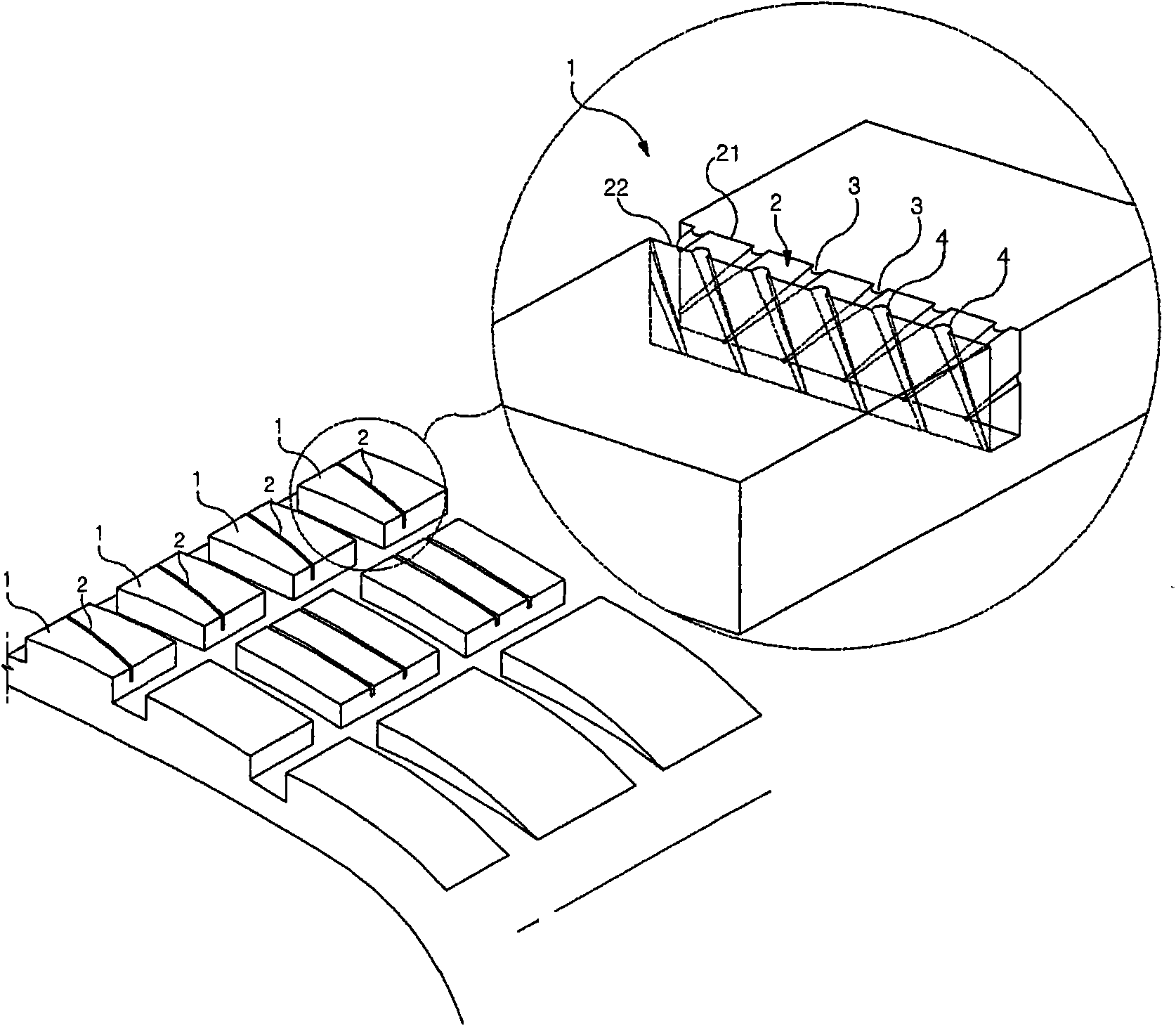
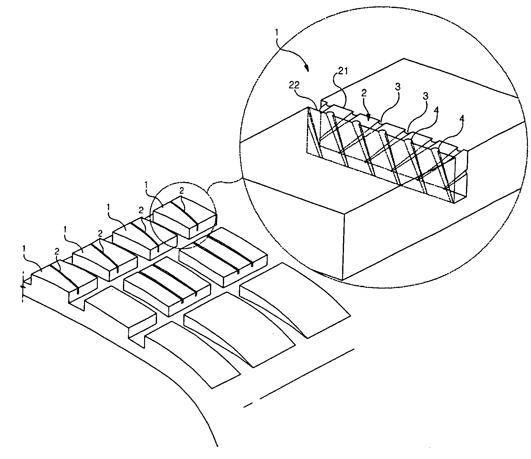
[0013] The automobile tire of the present invention is composed of a tread portion, sidewall portions on both sides of the tread portion, and spherical portions at both ends of the sidewall portion. A block 1 is formed on the contact surface of the tread portion, and a slit 2 is formed on the block 1 . In addition, inclined protrusions 3, 4 are formed on the wall surface of the slit 2. As shown in FIG.

[0014] In the present invention, the inclined protrusions 3, 4 formed on the wall surface of the slit 2 are on the two wall surfaces 21, 22 of the slit 2, starting from the upper section of the slit 2, not in the axial or vertical direction, but along the The downwardly inclined directions are respectively protrudingly formed.

[0015] In addition, in the present invention, the above-mentioned inclined protrusions 3 , 4 provided on the op...


PUM


Abstract

The invention relates to a kerf-improved tire used for an automobile, since kerfs are formed according to a mode of an around 1mm small width, in practical driving, spacings become smaller and expected performances can not be well played. The kerf-improved tire is characterized in that, separators formed by protruding bars are formed on two inner walls of the kerfs in a mode of X-shaped crosses, during driver, the two wall surfaces of the kerfs are provided with spacings, preventing reduction of grip force of tires.

Description

technical field [0001] This invention relates to automobile tires with improved slitting. More specifically, the present invention relates to an automobile tire with improved slits, in which partitions formed of protrusions are formed on both inner walls of the slits in an X-shaped crossing manner, and the slits are closed when running. There is an interval between the two wall surfaces of the tire, which can prevent the reduction of the grip performance of the tire. Background technique [0002] In order to improve traction (traction) and braking force, slits (kerf) are formed on the contact surface of automobile tires. However, since such slits are generally formed to have a narrow width of about 1 mm, there is a high possibility that both side walls separated by the narrow width will contact each other during actual driving. Therefore, it is difficult to maintain the space between the side walls of the slits considered in the design. [0003] Therefore, in order to mai...

Claims


Application Information

Patent Timeline
IPC IPC(8): B60C11/12
CPCB60C11/11B60C11/12B60C11/1218B60C2011/1245B60C2200/04
Inventor 田尚旼
Learn More