Automobile gear level switching device

A gear switching, vehicle technology, applied in the direction of control devices, transmission devices, vehicle components, etc., can solve problems such as inability to manually separate, gear damage, and reduced device durability.

Inactive Publication Date: 2004-10-20
AISIN AW CO LTD
View PDF3 Cites 16 Cited by
  • Summary
  • Abstract
  • Description
  • Claims
  • Application Information

AI Technical Summary

Problems solved by technology

[0012] However, at this time, manual separation is performed after the gears are separated mechanically, so simple manual separation cannot be performed.
In addition, since a mechanical separation mechanism is required, there are problems such as an increase in the size of the shift switching device and high cost.
In addition, due to the use of gear transmission torque, manual separation cannot be easily performed, and the setting position and method of manual separation are limited.
In addition, after the gear meshing with the worm gear is separated, it is necessary to mesh the gears again, which may damage the gears and reduce the durability of the device.

Method used


Image

  • Automobile gear level switching device
  • Automobile gear level switching device
  • Automobile gear level switching device

Examples


Embodiment approach 1

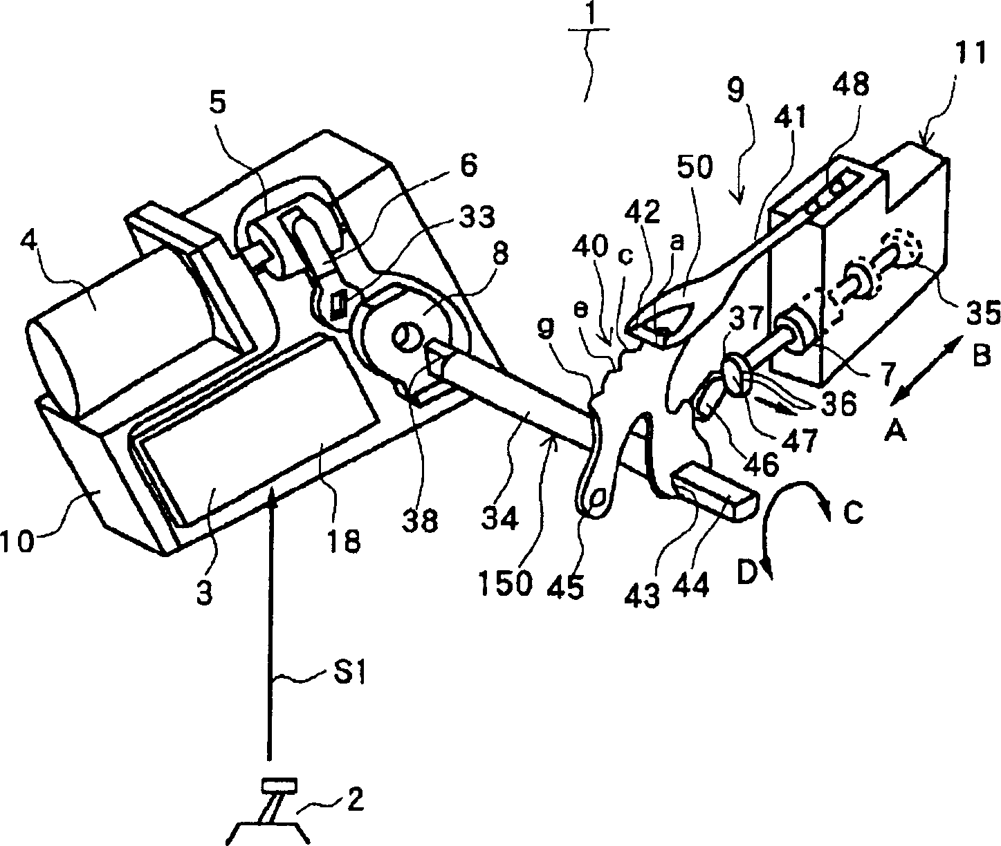
[0253] figure 1 As an example of the vehicle range switching device according to the present invention, the vehicle range switching device (hereinafter referred to simply as "the range switching device") 1 according to Embodiment 1 is shown. This figure is a perspective view schematically showing the overall structure of the range switching device 1 .

[0254] The range switching device 1 is incorporated into an automatic transmission (for example, a multi-stage automatic transmission or a continuously variable transmission (CVT)) mounted on a vehicle. Such as figure 1 As shown, the main structural components of the gear switching device 1 include: a shift lever 2 as a gear selection mechanism for the driver to select a driving gear, and an electric signal ( control signal), the motor 4 controlled according to the control signal from the first control mechanism 3, the conversion mechanism (transformation mechanism) 5 that converts the rotational motion of the motor 4 into a ...

Embodiment approach 2

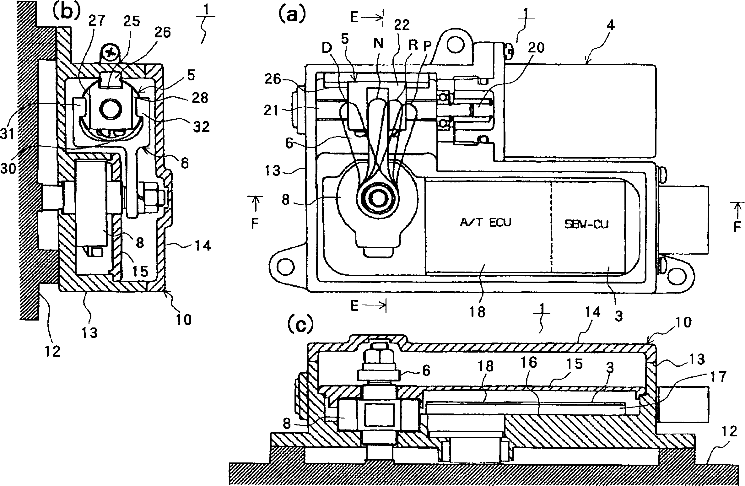
[0279] Figure 5 (a), (b), and (c) show the range switching device 50 related to this embodiment. These graphs in turn correspond to the above figure 2 (a), (b), (c). Additionally, with figure 2 The same parts shown in (a), (b) and (c) are given the same symbols and descriptions thereof are omitted.

[0280] In the present embodiment, the first control unit (SBW-CU) 3 and the second control unit (AT ECU) 18 are arranged in upper and lower layers.

[0281] The first control mechanism 3 is arranged on the bottom 16 of the casing body 13 of the casing member 10 , and the second control mechanism is arranged on the supporting member 51 provided above the first control mechanism 3 . The entirety of the first control mechanism 3 is arranged to overlap with the second control mechanism 18 .

[0282] According to this embodiment, it is possible to reduce the occupied area corresponding to the portion where the two overlap, compared to the horizontal arrangement. In addition, t...

Embodiment approach 3

[0285] Figure 6 (a), (b), and (c) show the range switching device 60 related to this embodiment. In the shift switching device 60 shown in the figure, spur gears 52 a and 52 b are installed between the output shaft 20 of the motor 4 and the ball screw shaft 21 of the conversion mechanism 5 .

[0286] A small-diameter spur gear 52a is fitted to the output shaft 20 of the motor 4, while a large-diameter spur gear 52b is fitted to the ball screw shaft 21, and these spur gears 52a, 52b mesh with each other.

[0287] In this way, the gear ratio can be enlarged, and thus the size reduction of the motor 4 can be achieved.


PUM


Abstract

A conversion mechanism 5 consists of a ball screw shaft 21, a ball nut 22, etc. The ball nut 22 is connected to a spool 7 via an arm member 6, a range control shaft 34 and a detent lever 40. A motor 40 is used for moving the spool 7 to a predetermined switching region of a plurality of switching regions via the conversion mechanism 5 and the arm member 6. Then, the detent mechanism 9 is used for further moving the spool 7 to a switching position to position and hold it. To provide a range switching device simply constructed and controlled to accurately change over a travel range.

Description

technical field [0001] The present invention relates to a vehicle gear switching device equipped with a so-called shift-by-wire system that sets a driving gear (for example, P, R, N, D) selected by a driver through a shift lever by an electric signal. Background technique [0002] For example, the driving gear of a vehicle with an automatic transmission is generally set by a driver by operating a shift lever to move a manual valve, thereby switching oil passages. At this time, the driving gear selected by the driver is set not by a mechanical wire or lever but by an electrical signal, which is known as a shift-by-wire (SBW) system (for example, refer to Patent Document 1). [0003] For example, a shift-by-wire (SBW) system using a feed screw device in Patent Document 2 and a shift-by-wire (SBW) system using a turbine in Patent Document 3 have been disclosed. [0004] It is well known that the feed screw device disclosed in Patent Document 2 itself can achieve a large reduct...

Claims


Application Information

Patent Timeline
Patent Type & Authority Applications(China)
IPC IPC(8): F16H25/20F16H25/24F16H27/08F16H59/02F16H59/08F16H61/28F16H61/32F16H63/38
CPCF16H2061/326F16H63/3466F16H2061/2869F16H2061/2884F16H61/32F16H2061/1288F16H61/12Y10T74/2003Y10T74/2011Y10T74/19251A47J47/04
Inventor 尾崎和久犬塚武细野智宏村濑和久田中玄昌
Owner AISIN AW CO LTD
Why Eureka
Try Eureka