Stern tube bush unit

A technology for stern tubes and bushings, which is applied in the direction of engine components, transmission devices with synchronous propulsion components, engine seals, etc., can solve the problems of reducing the space utilization rate of the rear side of the hull and increasing the overall length of the hull, etc., to achieve Improved assembly quality, easy installation, and improved assembly

Inactive Publication Date: 2011-05-25
SUNBO IND +1
View PDF6 Cites 3 Cited by
  • Summary
  • Abstract
  • Description
  • Claims
  • Application Information

AI Technical Summary

Problems solved by technology

[0004] In addition, when assembling the conventional stern tube liner unit to the hull, the space on the rear side of the hull is reduced due to the structure in whic...

Method used


Image

  • Stern tube bush unit
  • Stern tube bush unit
  • Stern tube bush unit

Examples


Embodiment Construction

[0045] Next, a preferred embodiment of the present invention will be described in detail with reference to the accompanying drawings.

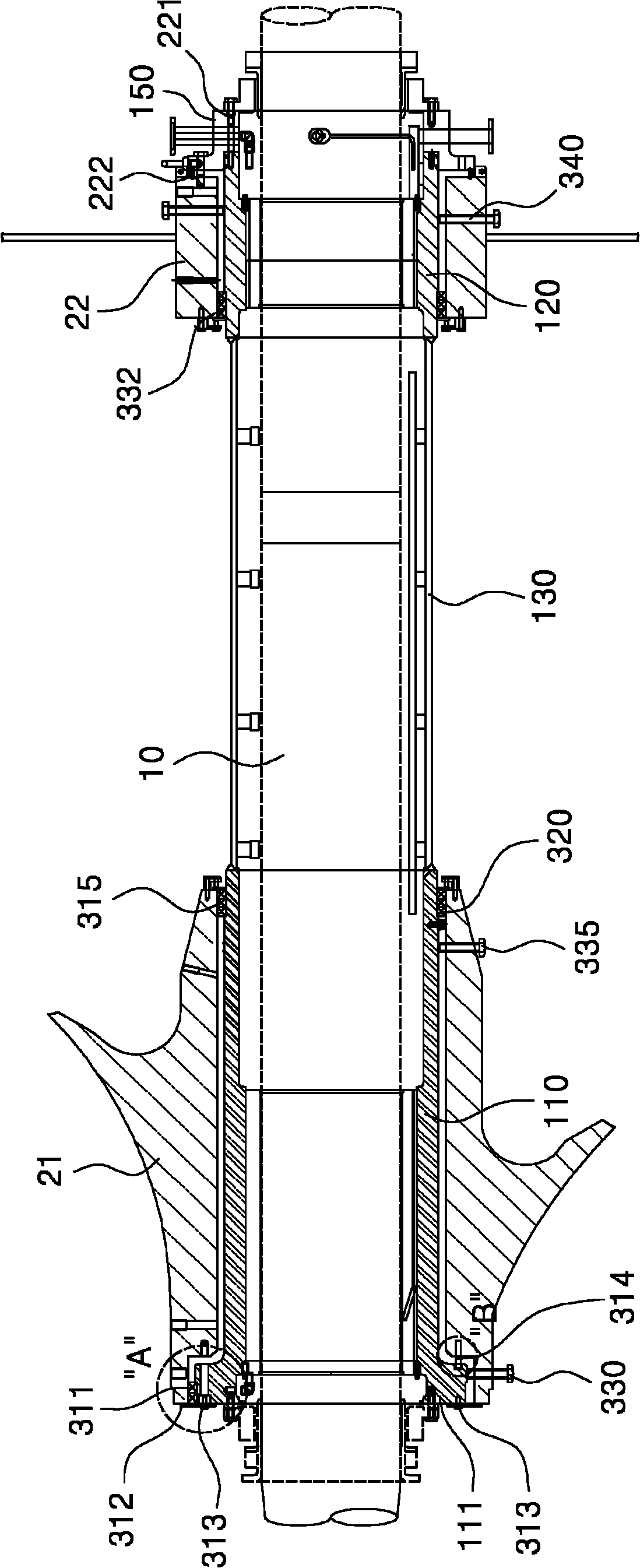
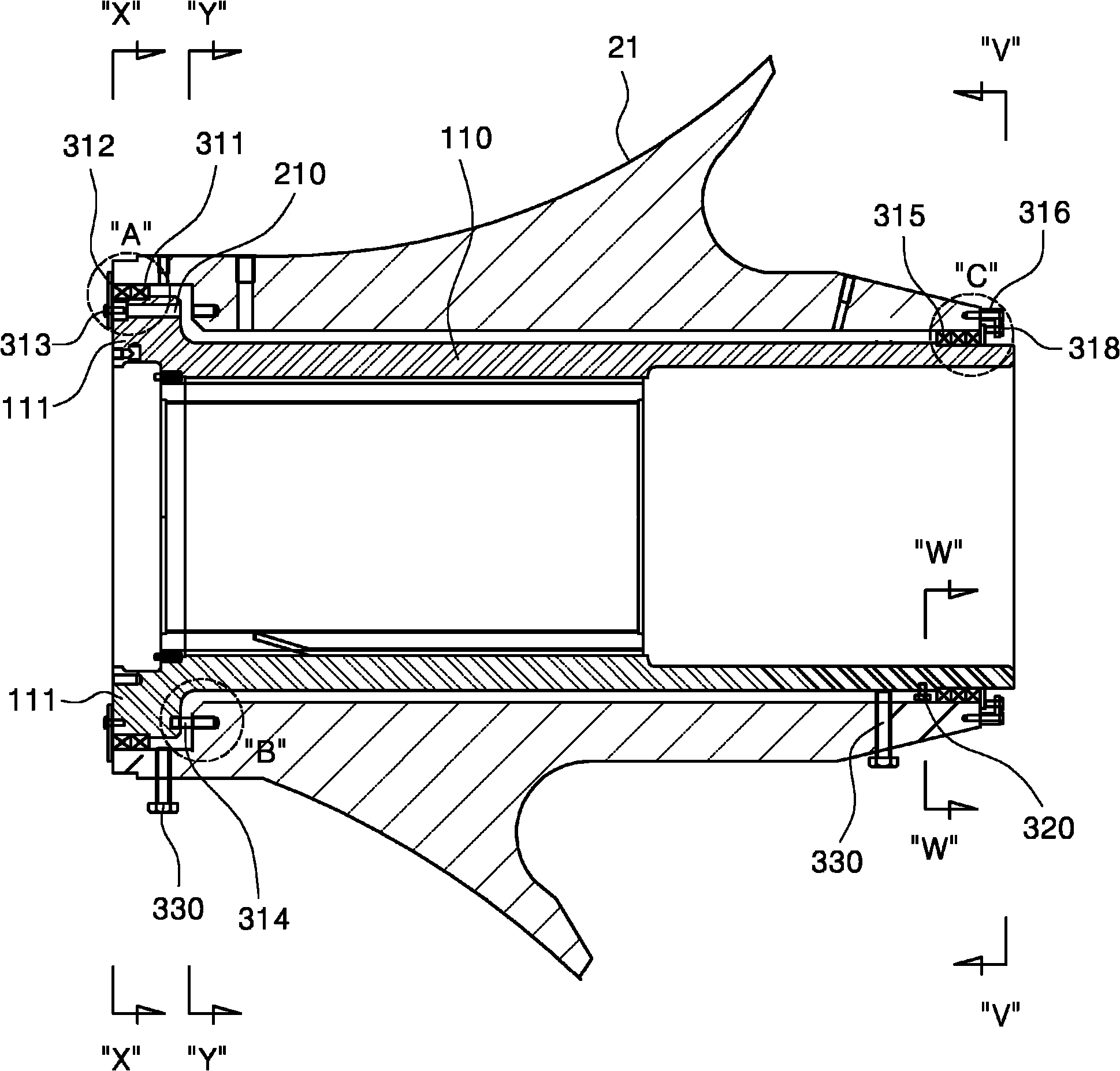
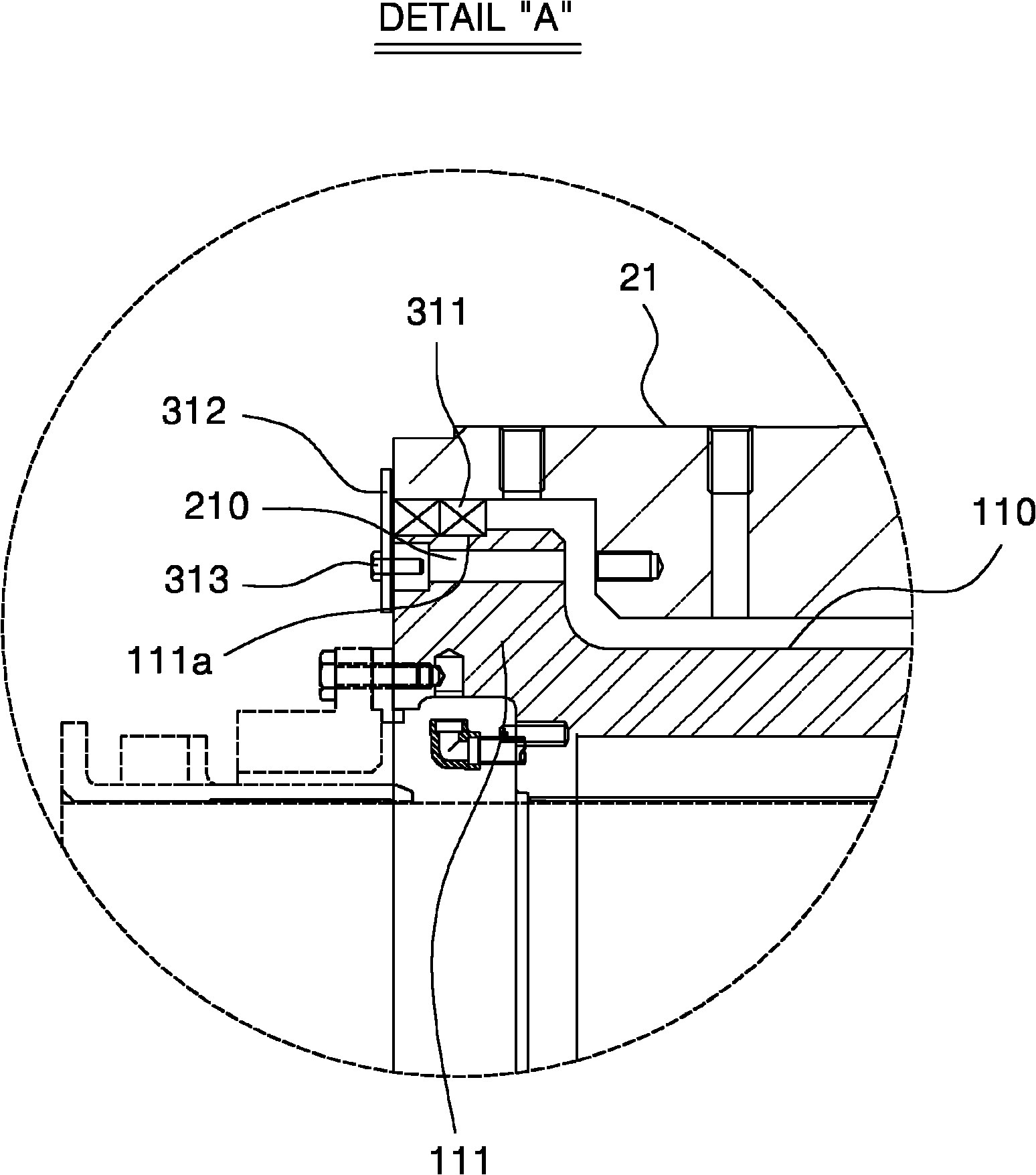
[0046] figure 1 It is a sectional view of an important part of an embodiment of the stern tube bushing unit of the present invention; figure 2 for figure 1 A detailed schematic diagram of important parts of the structure on the stern side of the hull shown; image 3 for figure 2 Detailed schematic diagram of part "A" of ; Figure 4 for figure 2 A detailed schematic diagram along the X-X cross-sectional direction of ; Figure 5 for figure 2 Detailed schematic diagram of part "B" of ; Figure 6 to Figure 8 for figure 2 Detailed schematic diagrams along the Y-Y, Z-Z, W-W cross-sectional directions of each; Figure 9 for figure 2 Detailed schematic diagram of part "C" of ; Figure 10 for figure 2 A detailed schematic diagram along the direction of the "V" section; Figure 11 for Figure 9 An example of the setting state of the...


PUM


Abstract

The present invention relates to a stern tube bush unit. When assembling the stern tube bush unit onto a hull, the rear surface of the stern of the hull and the rear surface of a first bush housing are disposed on the same plane, for coupling, and a rubber sponge is mounted between the bush housing and the hull for retaining sealing resin. Therefore, it is possible to increase the use of space at the rear side of the stern of the hull, and increase the sealing force of the resin which is filled between the hull and the bush housing. In addition, it is possible to firmly mount the stern tube bush unit at the precise position in the hull through a stable structure in a short time.

Description

technical field [0001] The present invention relates to a stern tube bushing unit installed between a propulsion shaft and a hull of a ship, in particular to improving the utilization rate of the space on the rear side of the hull and improving the sealing effect of the resin filled between the hull and the bushing unit, and The stern tube liner unit can be installed firmly and quickly with high assembly quality at the correct position in the hull to form a stable structure. Background technique [0002] In general, among various bearings supporting the propulsion shaft of a ship, a bush bearing (hereinafter referred to as a "stern tube bush unit") is used for the bearing interposed in the stern tube, and when assembling the above-mentioned stern tube When the bushing unit is used, the propeller’s own weight acting on the propulsion shaft, seawater buoyancy, thrust torque, etc. are considered to be assembled in a shaft-aligned manner so that the contact pressure with the pro...

Claims


Application Information

Patent Timeline
IPC IPC(8): B63H23/36F16J15/16
CPCB63B3/40B63H23/36F16J15/54
Inventor 崔金植
Owner SUNBO IND
Why Eureka
Try Eureka