Light guide plate, backlight module and display device thereof

A backlight module and light guide plate technology, applied in lighting devices, fixed lighting devices, optics, etc., can solve problems such as weakened light extraction efficiency, scratches on the optical film, and degradation of the optical rotation performance of the light guide plate 500, so as to maintain light output efficiency and improve The effects of tightness of fit and good light extraction efficiency

Inactive Publication Date: 2011-05-25
苏州茂立光电科技有限公司
View PDF8 Cites 3 Cited by
  • Summary
  • Abstract
  • Description
  • Claims
  • Application Information

AI Technical Summary

Problems solved by technology

[0005] In this way, the protrusions 420 around the micro-recess 410 will fall into the micro-recess 410 due to bending or collapse, and fill the micro-recess 410, resulting in deterioration of the light-guiding performance of the light guide plate 500
[0006] What's more, due to the phenomenon of slag splashing, these protrusions 420 may have a barb shape, so that when the light guide plate 500 is installed in the display device and overlapped with other optical films, the protrusions of the light guide plate 500 will not be visible. The object 420 will be unfavorable for the close adhesion of these optical films and the light guide plate, thereby weakening the light extraction efficiency, or the protrusion 420 of the light guide plate 500 may even cause these optical films to be scratched or punctured.
[0007] It can be seen that the optical microstructure of the above-mentioned light guide plate 500 still has inconveniences and defects, and needs to be further improved.
In order to solve the above problems, related fields have tried their best to find a solution, but no applicable method has been developed for a long time.

Method used


Image

  • Light guide plate, backlight module and display device thereof
  • Light guide plate, backlight module and display device thereof
  • Light guide plate, backlight module and display device thereof

Examples


Embodiment Construction

[0029] Below in conjunction with accompanying drawing and specific embodiment the present invention is described in further detail:

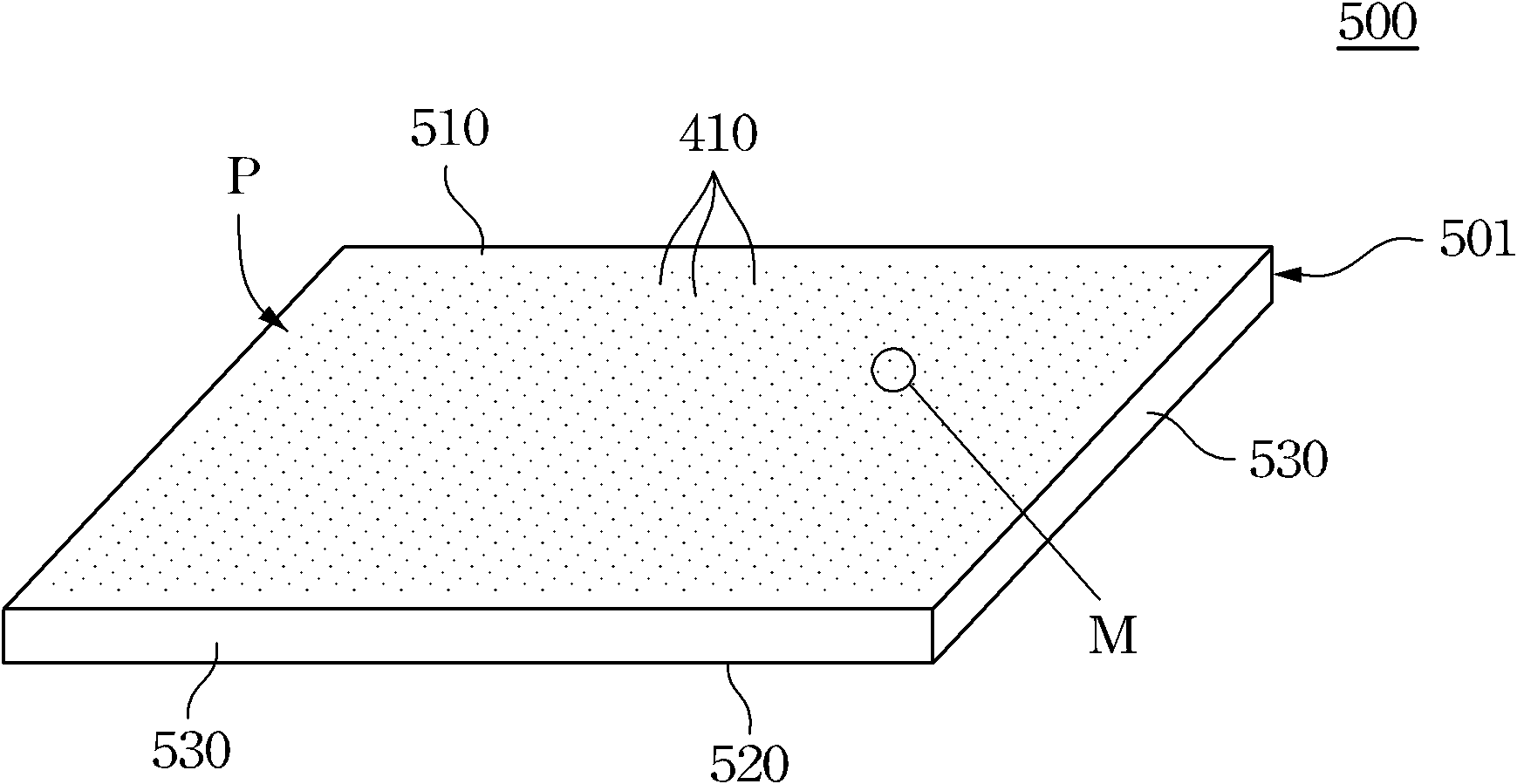
[0030] The invention discloses a light guide plate, a backlight module with the light guide plate and a display, which are used to provide good light guiding performance through the optical microstructure pattern on the surface of the light guide plate.

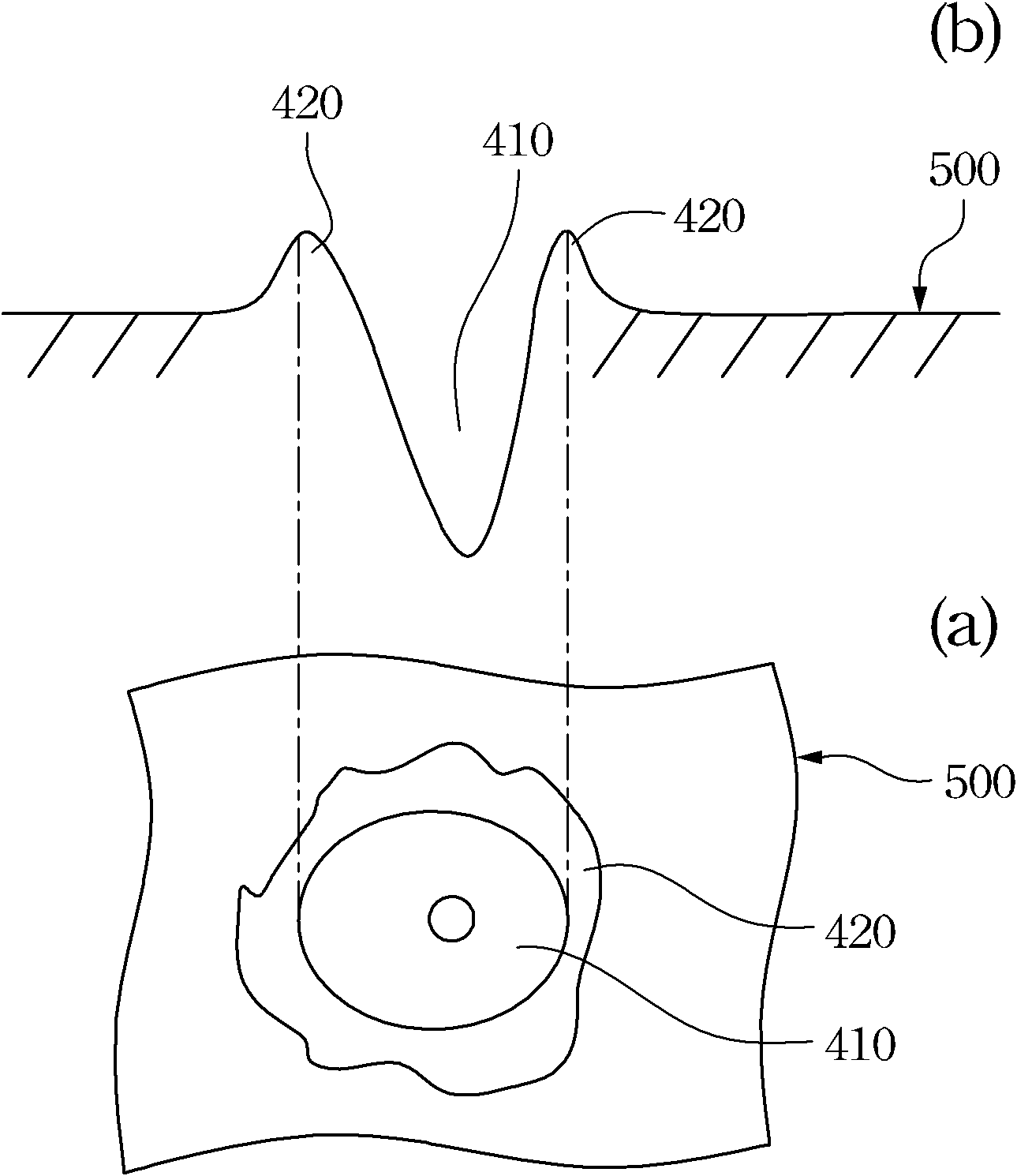
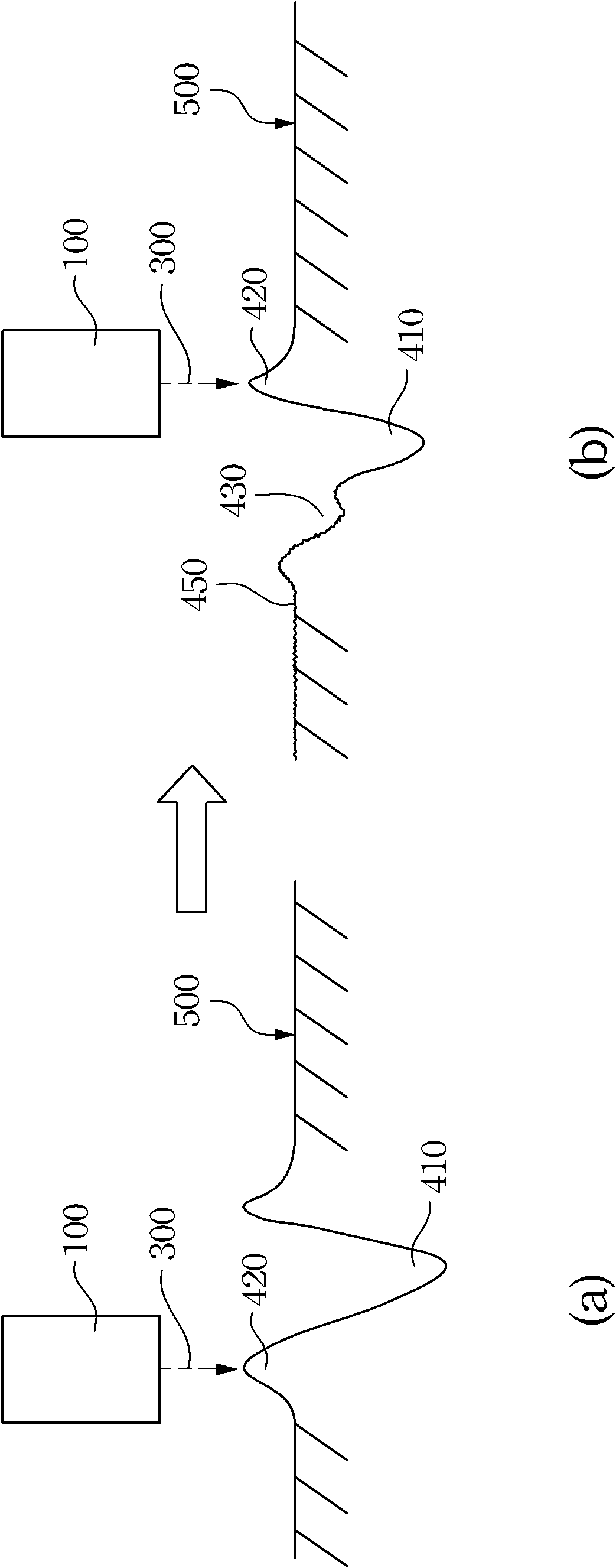
[0031] The invention discloses a light guide plate, a backlight module with the light guide plate and a display, which are used to reduce the chance of the protrusions on the periphery of the micro-holes falling off and filling the micro-holes.

[0032] The invention discloses a light guide plate, a backlight module with the light guide plate and a display, which are used to reduce or even prevent the light guide plate from scratching or piercing the optical film laminated thereon in the display device.

[0033] One embodiment of the present invention discloses a light guide plate. The light g...


PUM


Abstract

The invention relates to a light guide plate, a backlight module and a display device thereof. The light guide plate comprises a plate body and an optical microstructure pattern, wherein the optical microstructure pattern is distributed on the surface of the plate body and comprises a plurality of micro concave holes; the periphery of each of the micro concave holes is provided with at least one recessed part having a molten surface; and the depth of each recessed part is smaller than that of each micro concave hole. The invention has the advantages that: the possibility for protrusions at the peripheries of the micro concave holes to fall off to fill the micro concave holes can be reduced or avoided, and the optical guide rotation performance of the optical microstructure is prevented from being degraded after the light guide plate is manufactured. In addition, after the light guide plate is arranged in a display, the joint tightness of the light guide plate and an optical film is improved, the excellent light-extraction efficiency is kept, the optical film is prevented from being broken, and the service life of the product is prolonged.

Description

technical field [0001] The invention relates to a display device, in particular to a light guide plate and a backlight module in the display device. Background technique [0002] Traditionally, when making optical microstructures on the surface of the light guide plate, one of the methods is to use laser beams to bombard the light guide plate itself at high temperature, so that the surface of the light guide plate is melted by multiple laser beams to form many micro concave holes, so that it can be directly on the surface of the light guide plate. Fabricate optical microstructures. Because the apertures of these concave holes are of micron size, they are called micro concave holes. [0003] However, please refer to Figure 1, which shows a top view (a) and a cross-sectional view (b) of the appearance of a crater with micro-holes in the prior art. [0004] The use of laser beams to bombard the surface of the light guide plate 500 at high temperature will inevitably lead to t...

Claims


Application Information

Patent Timeline
Patent Type & Authority Applications(China)
IPC IPC(8): G02B6/00F21S8/00F21V8/00
Inventor 叶钧皓
Owner 苏州茂立光电科技有限公司
Why Eureka
Try Eureka