

Image forming apparatus
An image and equipment technology, applied in the field of image forming equipment, can solve problems such as instability and fluctuations
- Summary
- Abstract
- Description
- Claims
- Application Information
AI Technical Summary
Problems solved by technology
Method used
Image

Examples
Embodiment 1
[0081] Image 6 (a) and Image 6 (b) is an illustration of the electrode arrangement on the upstream side of the secondary transfer portion in Example 1. Figure 7 is a graphic illustration of the effect of the potentiometric plate. Figure 8 (a) and Figure 8 (b) is a diagram each showing an equivalent circuit on the periphery of the potential regulating plate. Figure 9 (a) and Figure 9 (b) is a graphical representation of the comparison of potential measurements in the absence and presence of a potential-regulating plate, respectively.
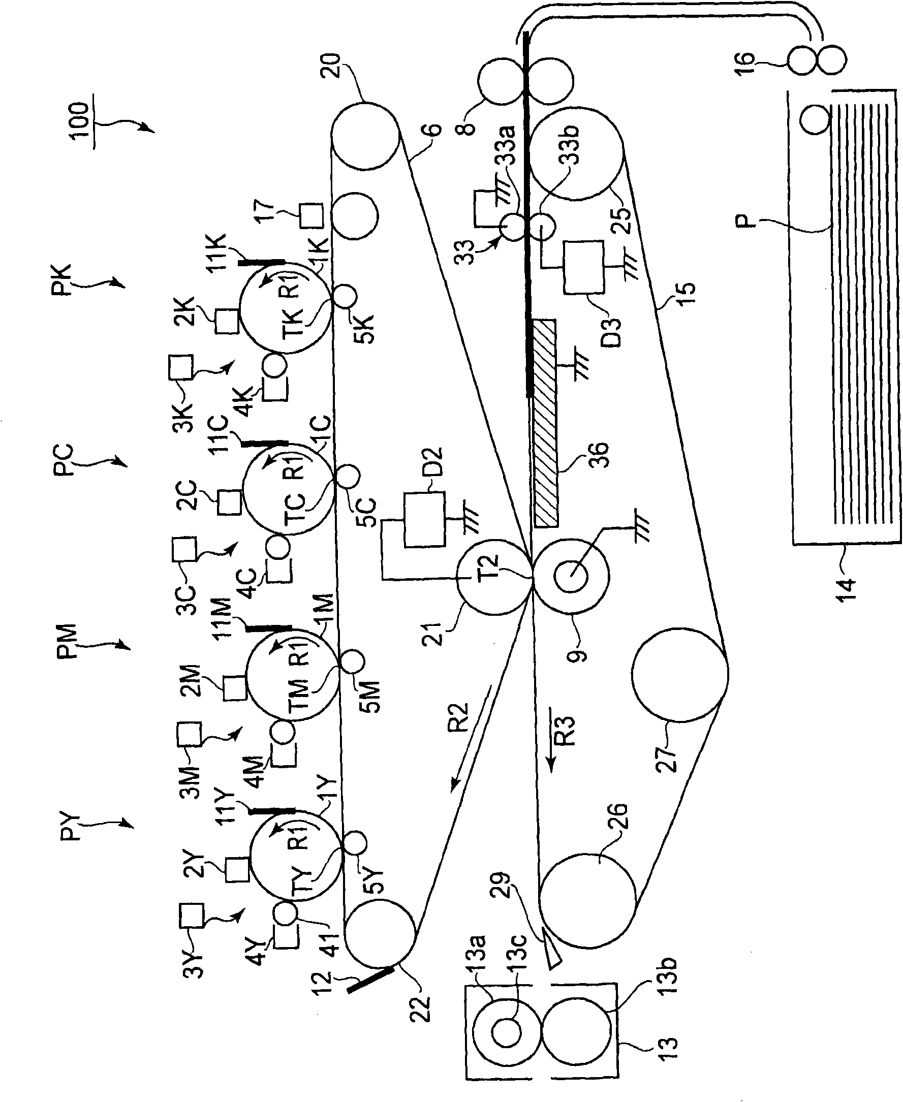
[0082] Such as figure 1 As shown, the transfer belt 15 extends around and is supported by the separation roller 26, the tension roller 27, and the entrance roller 25, which also serve as driving rollers, and is driven by the separation roller 26 so that the transfer belt 15 The printing belt 15 rotates at a process speed of 250-300 mm / sec in the direction indicated by the arrow R3.
[0083] The attraction roller 33 that controls th...
Embodiment 2
[0112] Figure 10 is an illustration of the structure of the image forming apparatus in Embodiment 2. Figure 11 (a) and Figure 11 (b) is an illustration of the electrode arrangement on the upstream side of the secondary transfer portion in Example 2. Figure 12 is a graphic illustration of the effect of the potentiometric plate. Figure 13 (a) and Figure 13 (b) is a diagram each showing an equivalent circuit on the periphery of the potential regulating plate. Figure 14 (a) and Figure 14 (b) is a graphical representation of the comparison of potential measurements in the absence and presence of a potential-regulating plate, respectively.
[0113] In addition to the voltage application method at the secondary transfer portion T2 and the arrangement of the potential regulating plate, figure 1 The image forming apparatus 100 shown in and Figure 10 The configuration of the image forming apparatus 100A shown in is equivalent. For this, in Figure 10 in, with figure...
Embodiment 3
[0134] Figure 15 is an illustration of the structure of the image forming apparatus in Embodiment 3. Figure 16 (a) and Figure 16 (b) is an illustration of the electrode arrangement on the upstream side of the secondary transfer portion in Example 3. Figure 17 is a graphic illustration of the effect of the potentiometric plate. Figure 18 (a) and Figure 18 (b) is a graphical representation of the comparison of potential measurements in the absence and presence of a potential-regulating plate, respectively.
[0135] by putting Figure 10 The potential adjustment plate 35 of the image forming apparatus 100A shown in the figure 1 The image forming apparatus 100B in this embodiment is constituted in the image forming apparatus 100 shown in . The other configurations are the same as in Embodiment 1, and the configuration and arrangement of the potential regulating plate 35 are the same as in Embodiment 2. Thus, in Figure 15 in, with figure 1 with Figure 10 Constit...
PUM
| Property | Measurement | Unit |
|---|---|---|
| Outer diameter | aaaaa | aaaaa |
| Resistance | aaaaa | aaaaa |
| Resistance | aaaaa | aaaaa |
Abstract
Description
Claims
Application Information