
Lens fixing device and optical pickup device

A lens fixing and lens technology, which is applied in the beam guiding device, optics, installation and other directions, can solve the problems of optical axis offset, complex and complicated structure of the lens holder 30, and achieves a simple structure, suppresses optical axis offset, and is easy to operate. Effect

Inactive Publication Date: 2011-05-25
SANYO ELECTRIC CO LTD +1
View PDF6 Cites 1 Cited by
  • Summary
  • Abstract
  • Description
  • Claims
  • Application Information

AI Technical Summary

Problems solved by technology

[0009] But when Image 6 In the structure of (b), since the hinge parts 31a, 32a are formed on the locking parts 31, 32, the structure of the lens holder 30 becomes complicated.
In addition, in order to mount the lens holder 30 on the base 40, complex operations are required, and the plate spring 50 must be assembled in a state where the surfaces S1, S2, and S3 are in contact with the corresponding surfaces of the base 40, and an adhesive must be used. 60 fixed lens holder 30
In addition, when the lens expands, if the forces applied from the leaf spring 50 and the forces applied from the hinge parts 31a and 32a are not balanced in the left and right directions in the same figure, the optical axis may shift in the left and right directions.

Method used


Image

  • Lens fixing device and optical pickup device
  • Lens fixing device and optical pickup device
  • Lens fixing device and optical pickup device

Examples


change example

[0068] Figure 5It is a figure which shows the modification example of a lens fixing device. In this modified example, two tapered protrusions 210a, 210b are formed on the front surface of the lens holder 200 as shown in FIG. The protrusions 210 a and 210 b are arranged at positions substantially aligned with the protrusions 301 a and 301 b in the Z-axis direction when the lens holder 200 is mounted on the mounting portion 300 . In addition, the height D1 of the protrusions 210a, 210b, as shown in the partially enlarged view of FIG. Compared with the gap D2, the amount of D3 is large.

[0069] In this modified example, the positioning of the lens portion 210 in the optical axis direction can be easily performed by the function of the protrusion 210a. i.e., as above image 3 When the lens holder 200 is inserted into the concave portion 303 , the protrusions 210 a and 210 b hit the back surface of the wall portion 302 , and the lens holder 200 receives a force in the directi...


PUM


Abstract

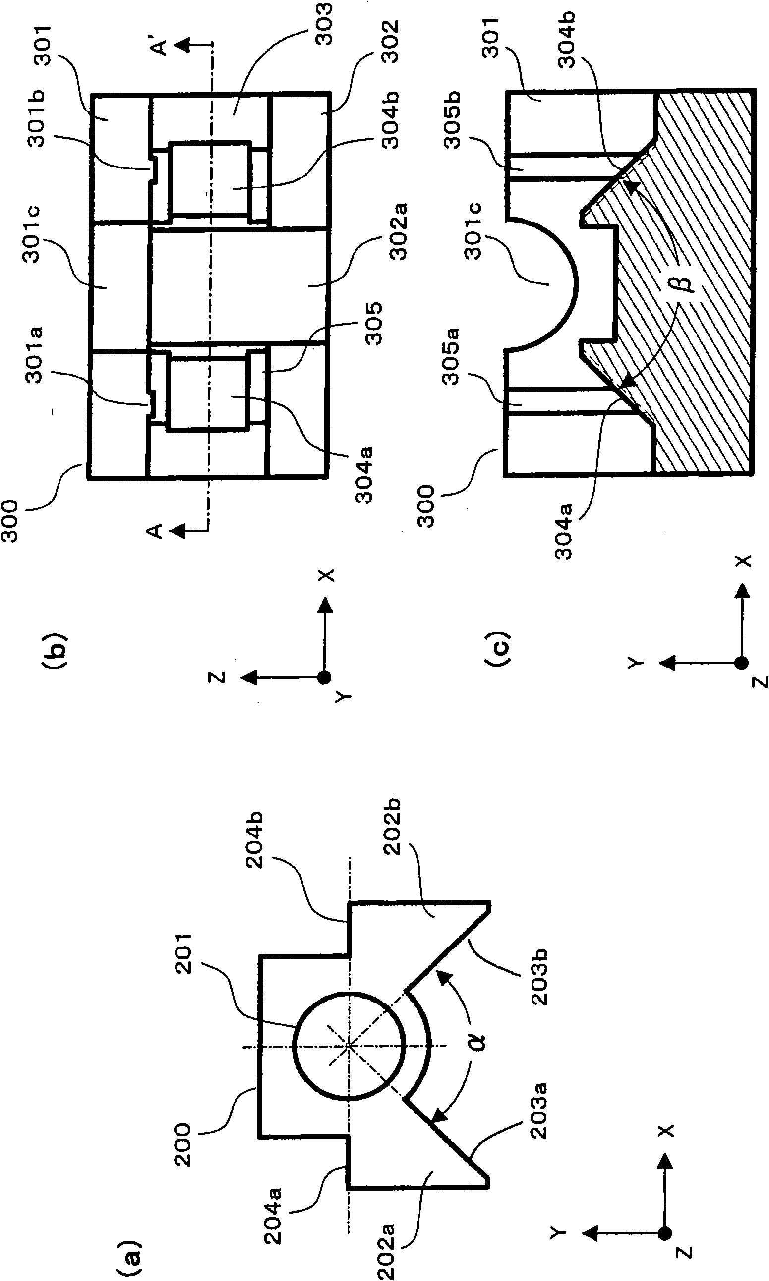
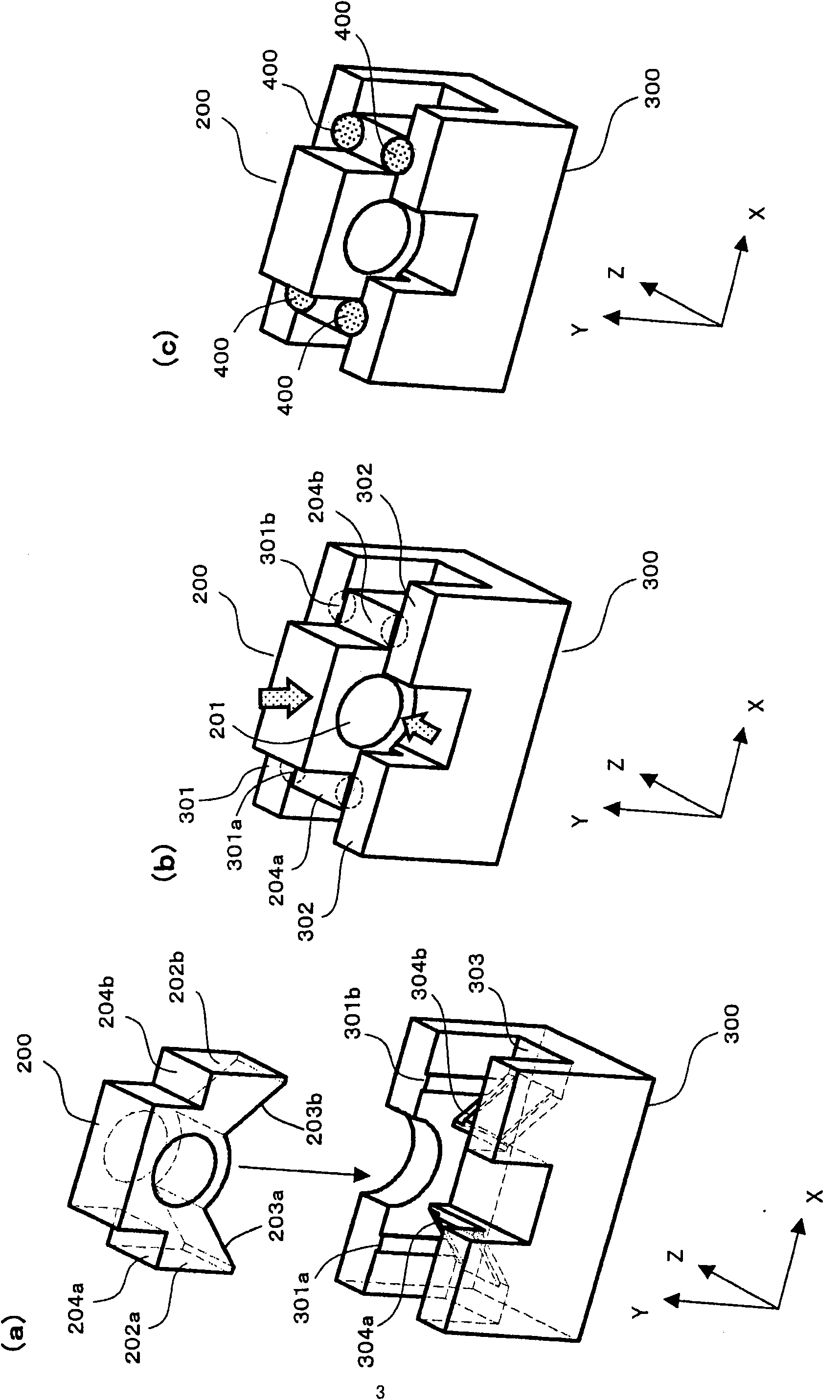
A lens fixing device includes a lens holder 200 having a lens (lens area 201) made of a resin, and a mounting portion 300. The lens holder 200 has two projections 202a, 202b. Each of the two projections 202a, 202b is formed with a guide surface 203a, 203b and a mounted surface 204a, 204b. A line of intersection of an extension of the guide surface 203a,203b of the projections and an extension of the mounted surface 204a, 204b of the projections in a plane direction is aligned with an optical axis of the lens area 201. The lens holder 200 is positioned with respect to a plane direction orthogonal to the optical axis by contact of the guide surfaces with receiving surfaces 304a, 304b of the mounting portion 300. The lens holder 200 is fixedly attached by an adhesive 400.

Description

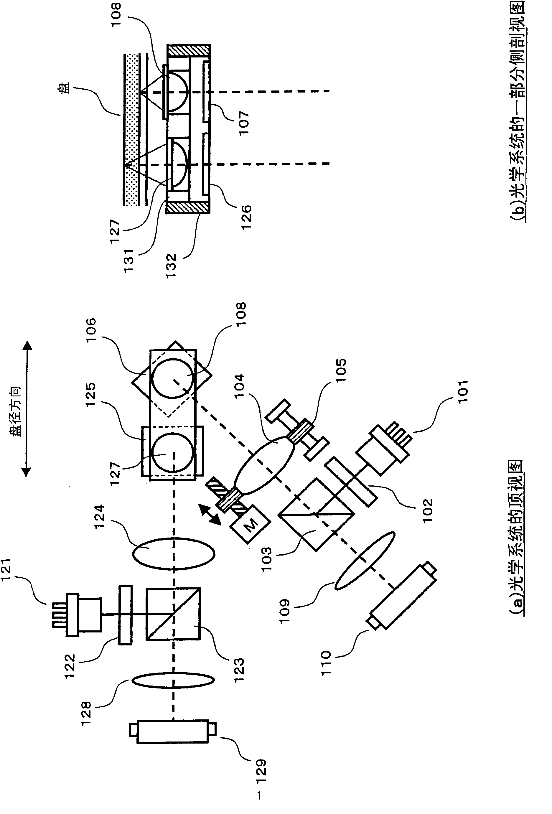
technical field [0001] The present invention relates to a lens fixing device for fixing a resin-made lens to a base, and an optical pickup device having the lens fixing device. Background technique [0002] In recent years, resin-made lenses are used in optical devices such as optical pickup devices. Such lenses are inexpensive and lightweight compared to conventional glass lenses. However, resin lenses are more likely to deform due to temperature changes than glass lenses, and the deterioration of optical characteristics caused by this has become an unsolved problem. [0003] Figure 6 (a) is a view of the fixing method of the resin lens viewed from the direction of the optical axis of the lens. In this form, the upper surface and the side surface are brought into contact with the base 20 , and the lens 10 is fixed to the base 20 . In this case, when the lens 10 expands around the optical axis due to a rise in temperature, the lens 10 is pressed by the surfaces 20a and 2...

Claims


Application Information

Patent Timeline
Patent Type & Authority Applications(China)
IPC IPC(8): G11B7/09G11B7/135G02B7/02
CPCG02B7/028G11B7/1376G11B7/1374G11B7/1378G11B7/22G11B7/1372G11B7/08
Inventor 加纳康行浅野贤二堀茂树
Owner SANYO ELECTRIC CO LTD
Learn More