
Telescopically collapsible scissor car jack
A lift and scissor technology, applied in the field of lifts, can solve the problems that hinder the reliable function of the lift, and achieve the effect of simple hand operation and small storage volume
- Summary
- Abstract
- Description
- Claims
- Application Information
AI Technical Summary
Problems solved by technology
Method used
Image

Examples
Embodiment Construction
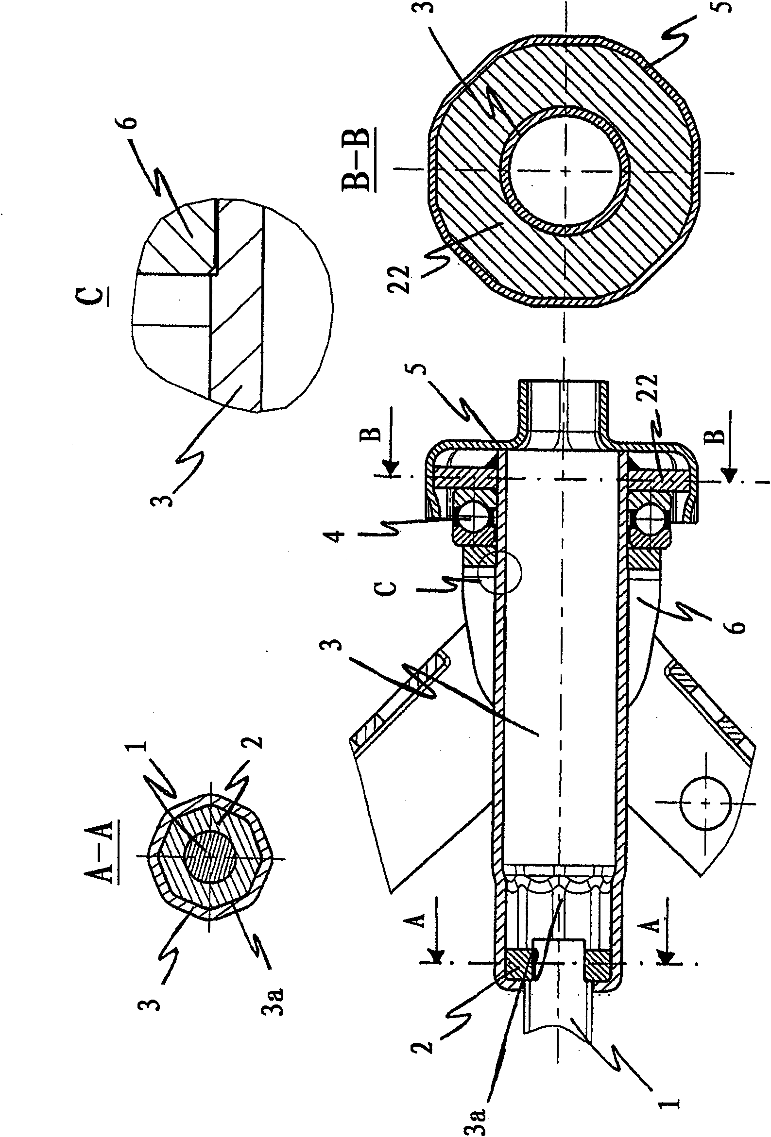
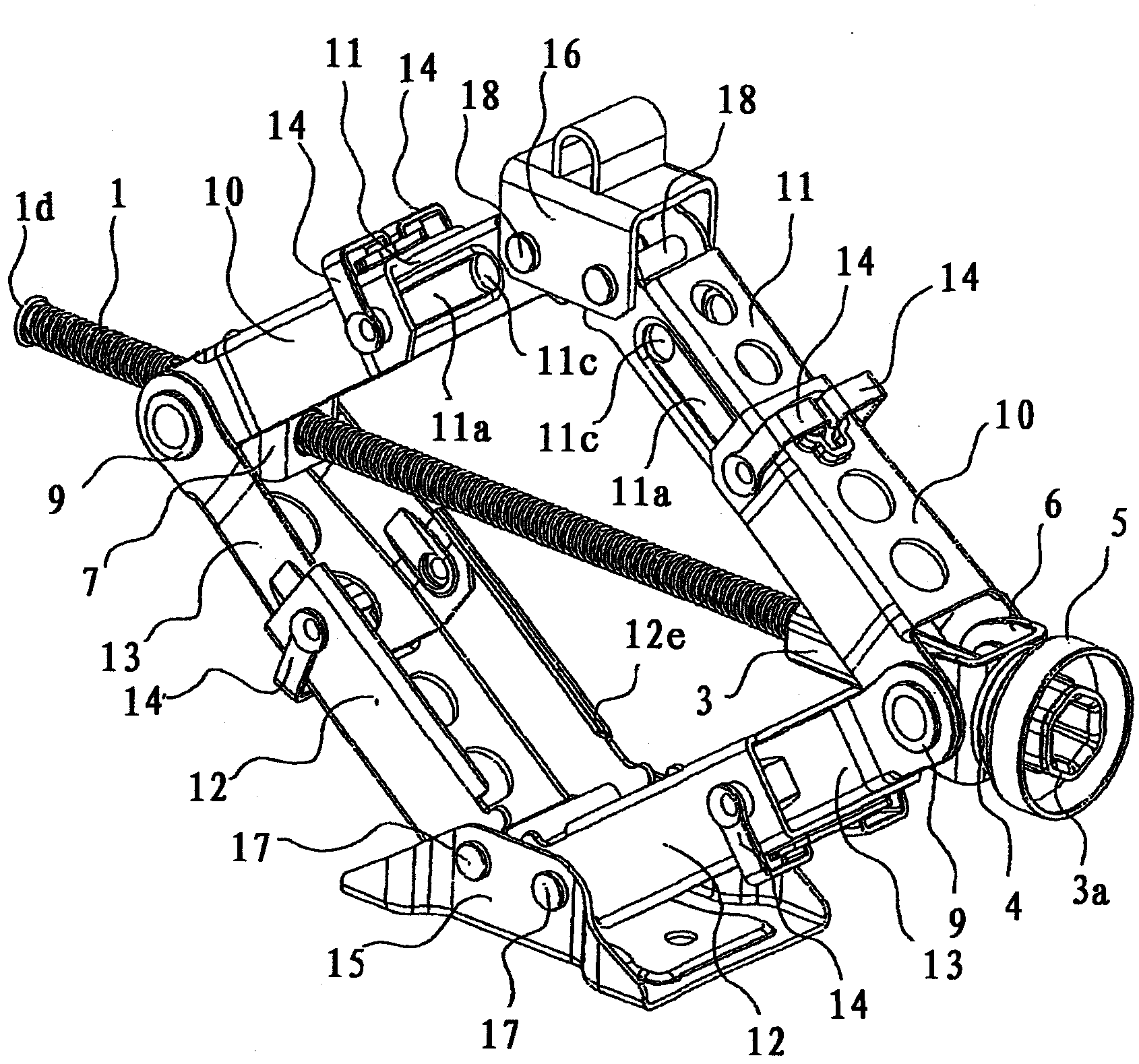
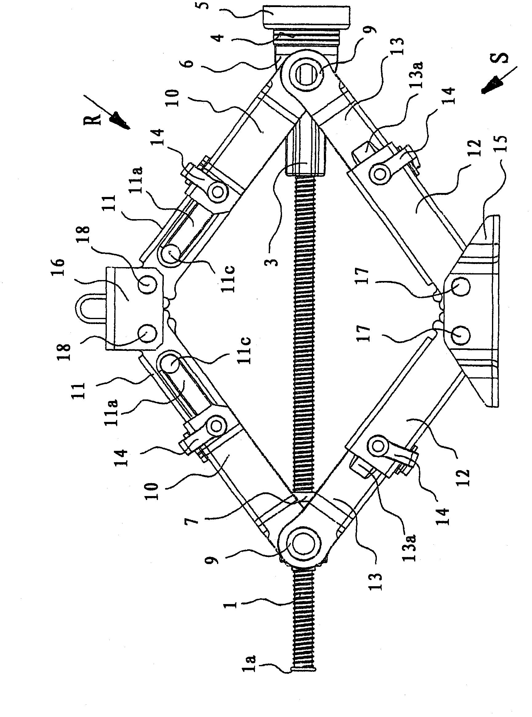
[0099] The spindle 1 is threaded and turned slightly at one end so that the spindle driver 2 can be pressed or welded in. On the other end, the mandrel 1 is partially extruded into 1a. The spindle driver 2 is a disk with a hole in the middle, which corresponds to the twisted part of the spindle. The outer circumference of the spindle driver 2 is polygonal (for example hexagonal) and is configured according to the inner polygon of the guide tube 3 .
[0100] The guide tube 3 is a thin-walled polygonal tube (for example a hexagonal tube) having a hole 3d with an inward radial wall 3a on one side and an outward radial wall 3b on the other side. The hole 3d is slightly larger than the diameter of the mandrel 1 . The spindle driver 2 is supported on the inner radial wall 3 a, wherein the spindle 1 can be moved axially within the guide tube 3 by means of the spindle driver 2 . By means of a polygonal allen wrench (eg a hexagonal allen wrench) positioned on the other side of the g...
PUM
 Abstract
Description
Claims
Application Information