
Drive device for a bending press

a technology of bending press and drive device, which is applied in the direction of presses, fluid-pressure actuators, telemotors, etc., can solve the problems of loss and unnecessary noise, leakage, etc., and achieve the effect of increasing the range of applications

Active Publication Date: 2013-01-01
TRUMPF MASCHEN AUSTRIA
View PDF17 Cites 2 Cited by
  • Summary
  • Abstract
  • Description
  • Claims
  • Application Information

AI Technical Summary

Benefits of technology

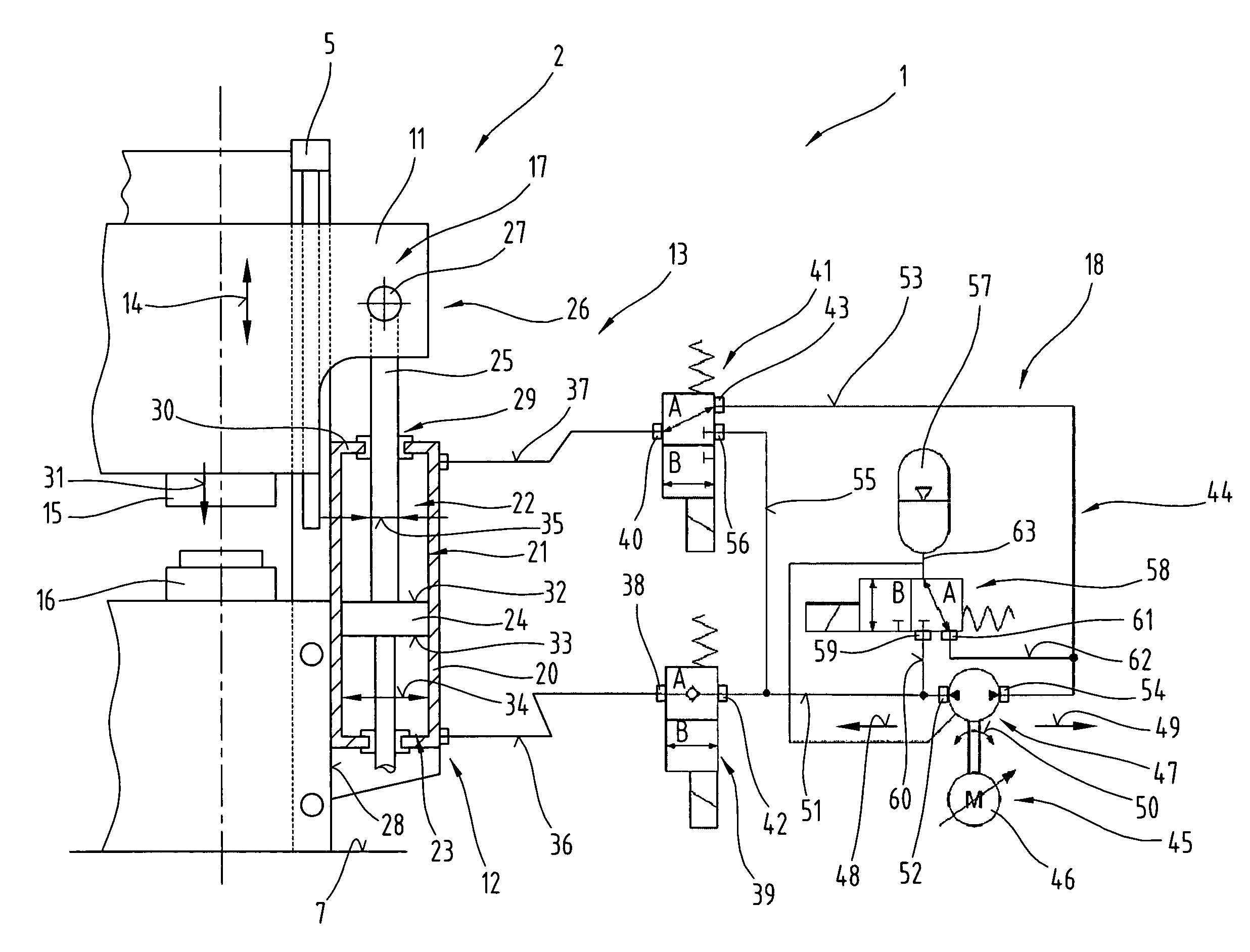
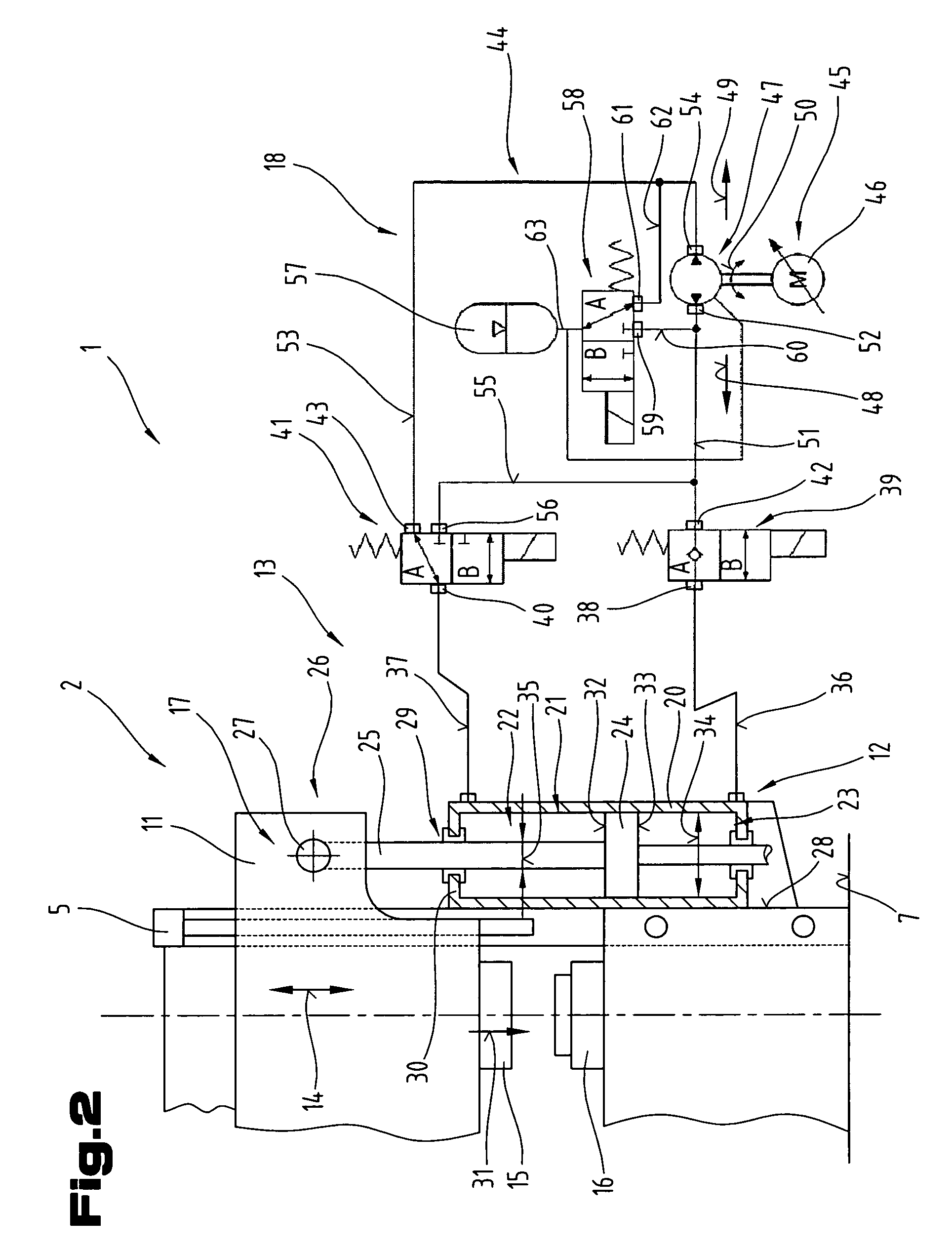
The invention is a drive device for a bending press that is highly effective, energy-saving, and modular in construction. It uses a closed hydraulic system with a ring line and medium store to reduce the power requirement and noise pollution. The pressure store can have a small volume, and a high speed is achieved with a small conveying volume of pressure medium. Small flow losses are avoided, and a rapid reaction is achieved for reversing operations. Different machine concepts can be adapted to the application, increasing the range of applications.

Problems solved by technology

A further disadvantage is that the electric drive motor and the connected hydraulic constant flow pump run during the entire operating period, which results in losses and unnecessary noise.
The latter may lead to leakages caused by permeability, breaks in the tubing or during the replacement of hydraulic components.

Method used


Image

  • Drive device for a bending press
  • Drive device for a bending press
  • Drive device for a bending press

Examples


Embodiment Construction

[0035]First of all, it should be noted that in the variously described exemplary embodiments the same parts have been given the same reference numerals and the same component names, whereby the disclosures contained throughout the entire description can be applied to the same parts with the same reference numerals and same component names. Also details relating to position used in the description, such as e.g. top, bottom, side etc. relate to the currently described and represented figure and in case of a change in position should be adjusted to the new position. Furthermore, also individual features or combinations of features from the various exemplary embodiments shown and described can represent in themselves independent or inventive solutions.

[0036]All of the details relating to value ranges in the present description are defined such that the latter include any and all part ranges, e.g. a range of 1 to 10 means that all part ranges, starting from the lower limit of 1 to the up...


PUM


Abstract

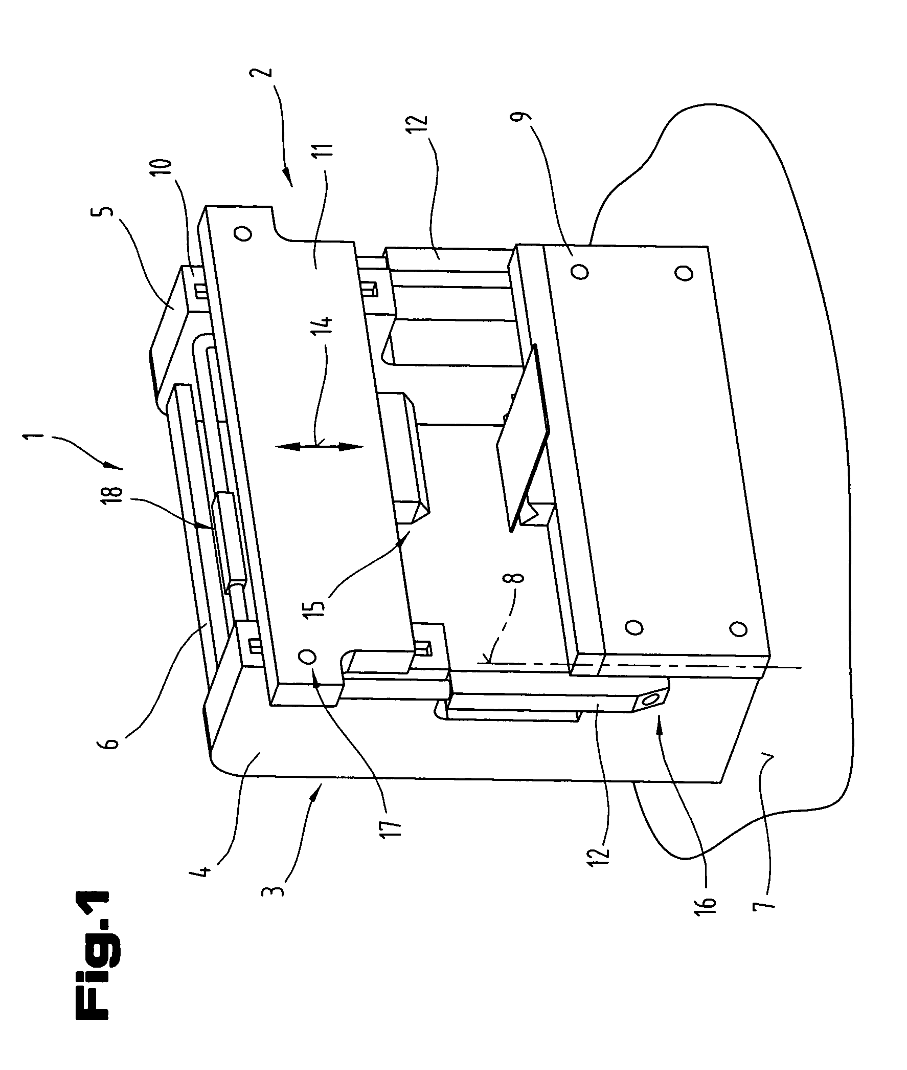
The invention relates to a drive device (1) for a bending press, in particular a folding press (2), comprising a press frame (3), a press table (9) and a press beam (11) that can be adjusted relative to the press table (9) via a hydraulic system (18) comprising a hydraulic pump (47), controlled drive motor (45), switch and control means and pressure lines and at least one pressure cylinder (12) which can be supplied with at least one pressure medium. The hydraulic system (18) forms a closed system together with a ring line (44) comprising the hydraulic pump (47), control valves (39, 41, 58, 84, 86, 87, 88, 89) and a pressure store (57). The ring line comprises a first line section (51) between a pressure chamber (23) of the pressure cylinder (12) and the hydraulic pump (47) and a second line section (53) between an additional pressure chamber (22) of the pressure cylinder (12) and the hydraulic pump (47). The pressure store (57) can optionally be in fluid connection via at least one of the control valves (58, 84, 86) with the first line section (51) or the second line section (53) to take up or release a storage volume of the pressure medium.

Description

CROSS REFERENCE TO RELATED APPLICATIONS[0001]This application is the National Stage of PCT / AT2008 / 000325 filed on Sep. 12, 2008 which claims priority under 35 U.S.C. §119 of Austrian Application No. A 1428 / 2007 filed on Sep. 12, 2007. The international application under PCT article 21(2) was not published in English.BACKGROUND OF THE INVENTION[0002]1. Field of the Invention[0003]The invention relates to a drive device, as described in the preamble of claim 1.[0004]2. The Prior Art[0005]From document WO 2006 / 101156 A1 a hydraulic drive device for a folding press and a method for operating the latter are known, according to which with an open hydraulic system for supplying operating cylinders a hydraulic pump is driven by a speed-controlled motor. The speed can be varied according to the different requirements for movement operations, such as rapid traverse, press traverse, emergency stop, return stroke, from standstill to maximum speed.[0006]From document JP 2002-147404 A a drive dev...

Claims


Application Information

Patent Timeline
Patent Type & Authority Patents(United States)
IPC IPC(8): B30B1/32
CPCB30B15/16B30B15/163F15B7/006F15B11/024F15B2211/20515F15B2211/20561F15B2211/212F15B2211/625F15B2211/7053F15B2211/88
Inventor RESCH, MARKUSSCHEIDL, RUDOLFLADNER, PETERLADNER, KARL
Owner TRUMPF MASCHEN AUSTRIA
Learn More