Method and apparatus for computer-aided identification of gripping objects

A computer-aided, object-oriented technology, applied in the direction of automatic disconnection of emergency protection devices, electrical program control, digital control, etc., can solve problems such as anti-pinch and low stability

Active Publication Date: 2016-08-03
CONTINENTAL AUTOMOTIVE TECH GMBH
View PDF5 Cites 0 Cited by
  • Summary
  • Abstract
  • Description
  • Claims
  • Application Information

AI Technical Summary

Problems solved by technology

However, this results in a disadvantageously low stability of the system against false triggering of the anti-trap (also called false reversal)

Method used


Image

  • Method and apparatus for computer-aided identification of gripping objects
  • Method and apparatus for computer-aided identification of gripping objects
  • Method and apparatus for computer-aided identification of gripping objects

Examples


Embodiment Construction

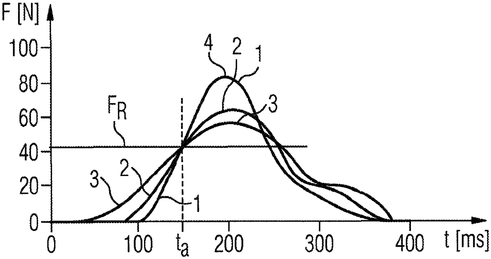
[0030] in figure 1 For three objects with different hardnesses, the force change curve in the clamped state is clarified, and the corresponding force F (unit is N) is plotted for time t (unit: ms); specifically, curve 1 is shown here The force change curve in the case of a spring stiffness of 65N / mm is shown. Curve 2 (curve 2 is relatively flat (with a slightly less steep rise) trend relative to curve 1) shows that the spring stiffness is 20N / mm The force change curve in this case, and curve 3 (curve 3 has the least steep rise) show the force change curve when the spring stiffness is 10 N / mm. In addition, a predetermined constant threshold value F is shown R , Where when the corresponding adjustment force 1, 2 or 3 reaches or exceeds the threshold or reference value F R At this time, the stopping process and the reversing process of the motor drive device (for example, the window lifter of the vehicle or the openable roof) that caused the force is started. However, for example,...


PUM


Abstract

In the case of computer-aided detection of clamping of objects when adjusting components of the vehicle using the actuating drive (6), the measured value associated with the actuating force (F) is compared with a predetermined threshold value (FR), When the threshold value is reached, the actuating movement is slowed down, stopped or reversed, in which case a spring stiffness correction term characterizing the hardness of the object is determined and taken into account in the comparison for correcting the actuating force (F) to the threshold value (FR) The relationship between.

Description

Technical field [0001] The present invention relates to a method and a device for computer-aided recognition of the entrapment of an object when adjusting components of a vehicle by means of an adjusting drive, wherein the measured value related to the adjusting force corresponds to a predetermined threshold value. By comparison, when the threshold is reached, the adjustment movement is caused to slow down, stop or reverse. Background technique [0002] When the components in the vehicle are manipulated by external forces, such as especially in electrically driven window regulators or openable roofs, an anti-pinch system is provided to limit the excess force generated by the adjustment drive. The anti-trapping system ideally directly recognizes a pinch situation by comparing the currently determined adjustment force value with a predetermined threshold value in a predetermined position during the adjustment process. If the adjustment force exerted by the motor rises above the th...

Claims


Application Information

Patent Timeline
Patent Type & Authority Patents(China)
IPC IPC(8): G05B19/19H02H7/085H02H3/44
CPCH02H3/44H02H7/0851
Inventor A.埃格尔S.霍尔兹曼R.莫拉维克
Owner CONTINENTAL AUTOMOTIVE TECH GMBH
Why Eureka
Try Eureka