Rubber punching machine

A punching machine and rubber technology, applied in metal processing and other directions, can solve problems such as affecting punching efficiency, and achieve the effect of improving punching efficiency

Active Publication Date: 2011-06-01
泛美汽车零部件(宁波)有限公司
View PDF5 Cites 10 Cited by
  • Summary
  • Abstract
  • Description
  • Claims
  • Application Information

AI Technical Summary

Problems solved by technology

However, this kind of punching machine is not suitable for punching rubber parts. After the punching is completed, the machine needs to be re-adjusted, which affects the punching efficiency.

Method used


Image

  • Rubber punching machine
  • Rubber punching machine
  • Rubber punching machine

Examples


Embodiment

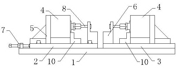
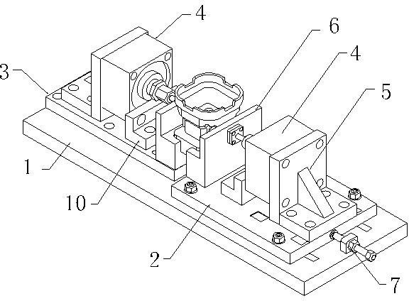
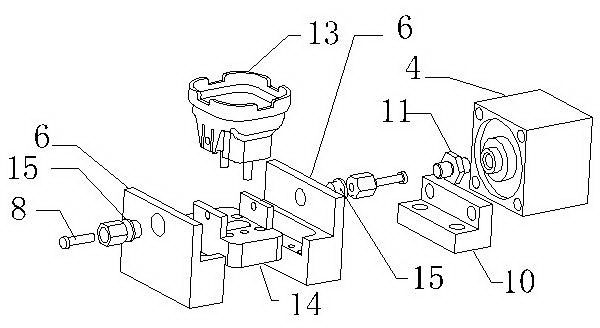
[0019] Example: A rubber punching machine of this example is figure 1 , 2 As shown, it includes a machine base plate 1, on which a product fixing seat is installed, and a left punching base plate 2 and a right punching base plate 3 installed opposite each other, and punching devices are installed on both the left punching base plate 2 and the right punching base plate 3 And the product fixing seat, the punching device includes a cylinder 4 and a punch 8. The axis lines of the punch 8 on the left punching base plate 2 and the punch 8 on the right punching base plate 3 coincide with each other. The split seat 6 is installed on the left punch bottom plate 2 and the right punch bottom plate 3. The split seat 6 is stepped. The lower step surface of the split seat 6 is provided with a concave mounting part, and the mounting part is provided with a screw Holes, such as image 3 As shown, there is a punch hole on the stepped wall of the split seat 6, a punch guide sleeve 15 is installed...


PUM


Abstract

The invention relates to a rubber punching machine, which comprises a base plate provided with a product fixing base and a left punching bottom plate and a right punching bottom plate arranged in opposite. Both the left and right punching bottom plates are provided with punching devices and the product fixing bases. Each punching device comprises a driving member and a punching head. The product fixing base comprises separated bases respectively arranged on the left and right punching bottom plates. The separated bases are provided with punching head holes matched with the punching heads corresponding to the punching head holes on position. At least one of the left and right punching bottom plates is a sliding plate in slip connection with the base plate. One side of the sliding plate is connected with a movable plate adjusting mechanism. The axial leads of the punching heads on the left and right punching bottom plates are superposed. The invention can be used for punching on both sides synchronously without adjusting the positions of the punching heads, thereby improving the punching efficiency.

Description

[0001] Technical field [0002] The invention relates to a punching machine, in particular to a rubber punching machine for punching holes on rubber parts. Background technique [0003] Chinese patent CN201427160 discloses a two-way punching device for shock absorber lining. The mold includes an upper mold base group and a lower mold base group. The upper mold base group is mainly composed of an upper mold base and an upper mold base arranged in sequence from top to bottom. The punch backing plate, the upper punch fixing plate, the upper discharging rubber and the upper discharging plate are composed. The lower mold seat group is mainly composed of symmetrically arranged from the bottom to the top and the components in the upper module. A movable die is arranged between the upper discharge plate and the lower discharge plate. However, this kind of punching machine is not suitable for punching rubber parts. After the punching is completed, the machine needs to be adjusted again, w...

Claims


Application Information

Patent Timeline
Patent Type & Authority Applications(China)
IPC IPC(8): B26F1/04
Inventor 史美杰陈叙尧
Owner 泛美汽车零部件(宁波)有限公司
Why Eureka
Try Eureka