
Novel pneumatic punching machine

A new type of pneumatic punching technology, which is applied in the field of pneumatic punching machines and new pneumatic punching machines, can solve the problems of low efficiency, low productivity, hidden safety hazards, etc., and achieve the effect of high punching efficiency and fast action speed

Inactive Publication Date: 2010-09-15
吴远东
View PDF0 Cites 8 Cited by
  • Summary
  • Abstract
  • Description
  • Claims
  • Application Information

AI Technical Summary

Problems solved by technology

Although the method of using electric hand drill to drill holes has greatly improved the efficiency compared with the method of manual punching, when there are many holes to be manufactured, the method of using electric hand drill still feels inefficient, such as in the construction of steel structure engineering. In construction installation, bridge construction installation, and sheet metal structural parts manufacturing, there are a large number of holes that need to be made. At present, in these industries, the hole making is basically the method of electric drill drilling, which has the defect of low productivity. At the same time, the method of electric drill drilling still has certain potential safety hazards in some specific places, such as the construction and installation of underground coal mines, the construction and installation of gas stations, and the construction and installation of other corresponding occasions.

Method used


Image

  • Novel pneumatic punching machine
  • Novel pneumatic punching machine

Examples


Embodiment Construction

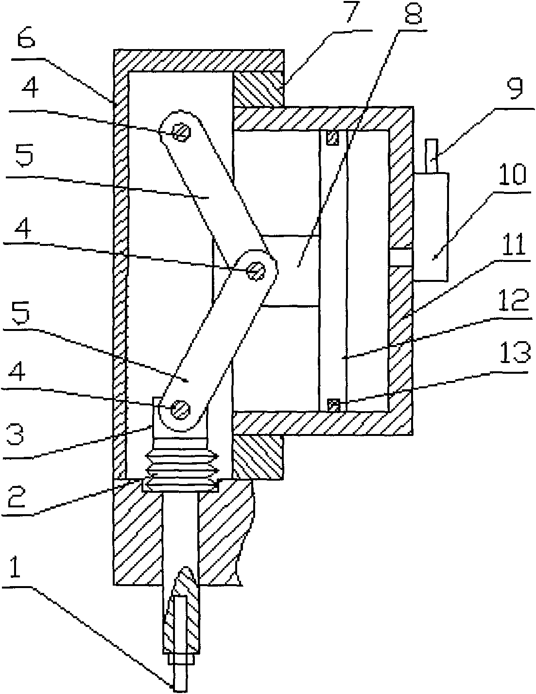
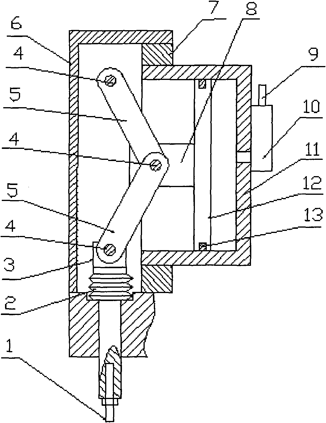
[0008] After installing the belleville springs (2) of appropriate quantity and specification on the punch (3), install the punch (3) on the bracket (6) correctly, and connect the two connecting rods (5) with the pin shaft (4 ) are correctly hinged with the bracket (6) and the punch (3) respectively. Install the flange sleeve (7) on the bracket (6), and install the cylinder assembly consisting of the piston rod (8), piston (12), cylinder (11) and sealing ring (13) on the flange sleeve (7). ) above. Use the pin shaft (4) to correctly hinge the two-section connecting rod (5) and the piston rod (8), install the quick air release valve (10) on the cylinder body of the cylinder or other appropriate positions, and place the quick air release valve ( 10) Install the air inlet joint (9) on the top, and install the drill bit (1) on the top of the punch (3).


PUM


Abstract

The invention relates to a novel pneumatic punching machine. The novel pneumatic punching machine is characterized in that a punch head is exactly arranged on a bracket after adequate quantity and specifications of butterfly springs are arranged on the punch head; two sections of connecting rods are exactly articulated with the bracket and the punch head through pin shafts; a flange sleeve is arranged on the bracket; a cylinder assembly comprising a piston rod, a piston, a cylinder and a seal ring is arranged on the flange sleeve; the two sections of connecting rods are exactly articulated with the piston rod by adopting pin shafts, a rapid release valve is arranged on a cylinder body or other appropriate positions of the cylinder, an air inlet connector is arranged on the rapid release valve, and a drill bit is arranged on the punch head.

Description

technical field [0001] The invention relates to a pneumatic punching machine, in particular to a novel pneumatic punching machine. It belongs to the technical field of mechatronics tools. Background technique [0002] At present, the main method of making holes on thin metal sheets is to use a hand electric drill to drill holes or to punch holes by hand. Although the method of using electric hand drill to drill holes has greatly improved the efficiency compared with the method of manual punching, when there are many holes to be manufactured, the method of using electric hand drill still feels inefficient, such as in the construction of steel structure engineering. In construction installation, bridge construction installation, and sheet metal structural parts manufacturing, there are a large number of holes that need to be made. At present, in these industries, the hole making is basically the method of electric drill drilling, which has the defect of low productivity. Sim...

Claims


Application Information

Patent Timeline
IPC IPC(8): B21D28/24
Inventor 吴远东
Owner 吴远东
Learn More