Punching and molding die and punching and molding method of workpieces

A stamping forming and die technology, applied in forming tools, punching tools, manufacturing tools, etc., can solve the problems of occupying punching machines, time-consuming and labor-intensive, low efficiency, etc., and achieve the effect of improving punching efficiency

Pending Publication Date: 2019-01-04
东莞中集专用车有限公司
View PDF0 Cites 8 Cited by
  • Summary
  • Abstract
  • Description
  • Claims
  • Application Information

AI Technical Summary

Problems solved by technology

However, mold replacement requires manual dismantling of one set of molds and installation of another set of

Method used


Image

  • Punching and molding die and punching and molding method of workpieces
  • Punching and molding die and punching and molding method of workpieces
  • Punching and molding die and punching and molding method of workpieces

Examples


Embodiment Construction

[0037] In order to further illustrate the principle and structure of the present invention, preferred embodiments of the present invention will now be described in detail with reference to the accompanying drawings.

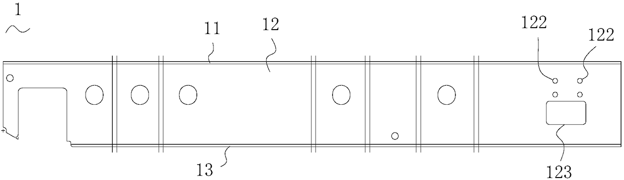
[0038] The stamping die of the present application is used to realize continuous punching and / or press forming of multiple holes of the workpiece. The structure of the stamping die of the first embodiment of the present application will be described in detail below in conjunction with a workpiece 1 to be punched.

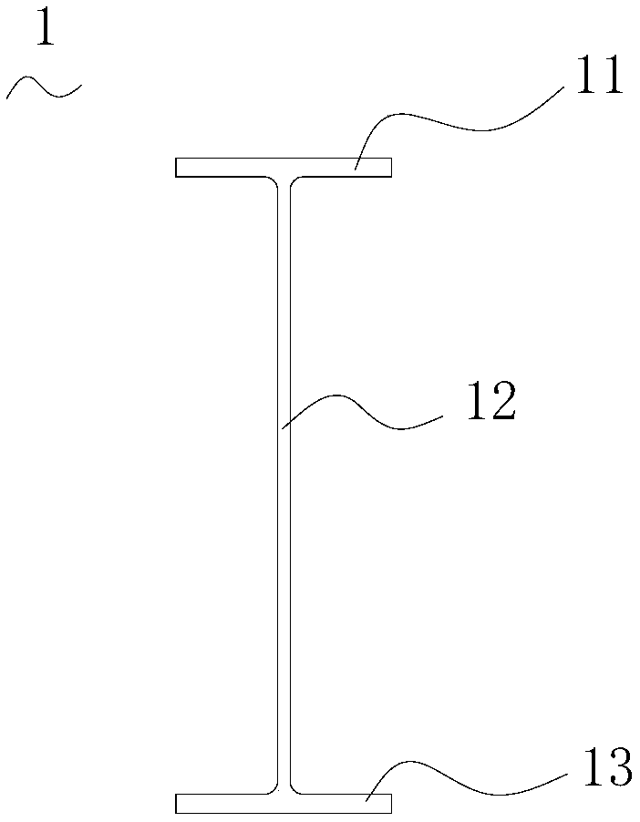
[0039] Such as figure 1 with figure 2 As shown, the workpiece 1 to be punched is an I-beam, and the I-beam includes: an upper wing plate 11, a lower wing plate 13, and a web 12 vertically connected between the upper wing plate 11 and the lower wing plate 13. The web 12 has a plurality of holes to be punched out. There are a plurality of holes near the right end in the figure, that is, four round holes 122 with a smaller diameter and one square hole ...


PUM


Abstract

The invention discloses a punching and molding die and a punching and molding method of workpieces. The punching and molding die comprises a concave die component, a convex die component and at leastone insertion plate, wherein the concave die component comprises a plurality of concave dies embedded in a concave die fixing plate; the convex die component comprises a plurality of convex dies mounted in a convex die fixing plate; at least one convex die is a switchable convex die and is slidably mounted in a convex die switching hole; at least one insertion plate cushion is arranged at the topend of the switchable convex die; the insertion plate is inserted in an insertion groove; the insertion groove is communicated with the convex die switching hole. The punching and molding method is characterized by arranging the insertion plate which can be pulled out and inserted at the top end of at least one convex die used for punching or molding, selectively pulling and inserting the insertion plate so as to repeatedly and continuously punch or mold the workpieces. The punching and molding die and the method thereof are capable of rapidly switching, punching or molding a plurality of holes in close distance or multiple groups of irregularly-distributed and equidistant or non-equidistant combined holes on a die, so that the punching and molding efficiency can be improved.

Description

technical field [0001] The invention relates to a mold, in particular to a stamping mold. Background technique [0002] In industrial production, some parts have multiple identical or different holes to be punched, and some holes are very close to each other, such as figure 1 As shown, the workpiece has four round holes 122 to be punched and one square hole 123 to be punched, and the distance H between the two round holes and the square hole is very close, only about a dozen millimeters, and many pre-realized For punching each hole at one time, it is necessary to intensively design multiple sets of concave-convex dies on the movable platen and fixed platen of the mold. Each set of concave-convex dies corresponds to punching one hole. Both the die and the punch must be designed very compactly, and if the die or the punch is too compact, the distance between the dies will be too small, the impact resistance will be poor, and the service life of the die will be affected. [0...

Claims


Application Information

Patent Timeline
IPC IPC(8): B21D28/34B21D28/24B21D37/10B21D22/02
CPCB21D28/34B21D22/02B21D28/243B21D37/10
Inventor 杨灿高承文洪光张家境胡江明魏振军
Owner 东莞中集专用车有限公司
Why Eureka
Try Eureka