Single beam girder erecting machine

A bridge erecting machine, single girder technology, used in bridges, bridge construction, erection/assembly of bridges, etc.

Inactive Publication Date: 2011-06-01
江西蓝天学院
View PDF5 Cites 13 Cited by
  • Summary
  • Abstract
  • Description
  • Claims
  • Application Information

AI Technical Summary

Problems solved by technology

Common railway bridge erecting machines are mainly double-girder bridge erecting machines, which are characterized by large wheel pressure, heavy weight and high cost
However, the latest single-girder bridge-erecting machine in foreign countries is a top-loading type. When the beam transport vehicle feeds the beam, the outriggers of the machine need to be turned up to allow the beam to pass through. The structure and operation are complex and difficult to manufacture.

Method used


Image

  • Single beam girder erecting machine
  • Single beam girder erecting machine
  • Single beam girder erecting machine

Examples


Embodiment Construction

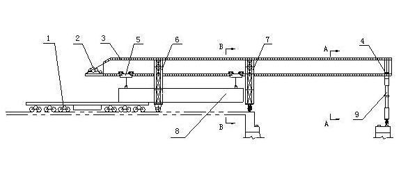
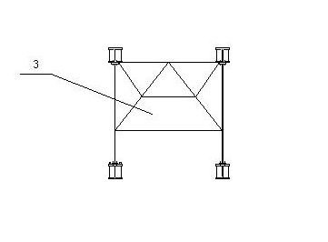
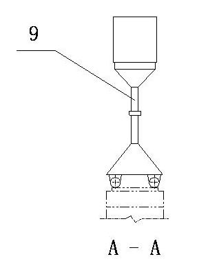
[0014] A single girder bridge erecting machine, comprising a main girder 3, a girder transporting vehicle 1, a trolley 5, a front outrigger 9, a middle outrigger 7, a rear outrigger 6 and a lifting mechanism 2, the main girder 1 is composed of four H-shaped steel and The steel plates are connected to form a single beam. The H-shaped steel at the lower end of the main beam 1 is provided with a square steel track. The trolley 5 is suspended on the square steel track on the H-shaped steel at the lower end of the main beam 1. The trolley frame passes through on both sides. Pin shafts 12 are connected to achieve three-point statically indeterminate balance. The trolley 5 enables the adjacent symmetrically suspended wheel treads to be self-adjustable on rail surfaces of different heights through the eccentric shaft 13, thereby ensuring that the wheel pressure is balanced. The front outrigger 9 is a single outrigger, which is composed of a hydraulic telescopic oil cylinder, a rotating...


PUM


Abstract

The invention relates to a single beam girder erecting machine, which comprises a girder, a trolley, a front landing leg and a rear landing leg. Four H beams are connected with steel plates to form a single beam girder. The H beams at the lower end of the girder are provided with square steel rails. A trolley is arranged on the square steel rails on the H beams at the lower end of the girder in a through suspended mode. The front landing leg is a single landing leg. Both the rear landing leg and a middle landing leg are O-shaped landing legs. The front landing leg is pressed against the girder in the working process. Both the rear landing leg and the middle landing leg are connected with the girder through high strength bolts. Due to the adoption of a through suspended structure, the single beam girder erecting machine has low height, can pass through a tunnel smoothly, has a small machine type, light weight and uniform and low wheel pressure and is convenient to assemble, disassemble and maintain. When being carried and transported by a girder transporting vehicle, the erecting machine is only needed to be disassembled partly. Big and small trolleys can move longitudinally and transversely. A track gauge can be adjusted. The single beam girder erecting machine can be used for erecting a full-span single or double wire box girder.

Description

technical field [0001] The invention relates to a single girder bridge erecting machine. Background technique [0002] With the development of high-speed railways and highways, the erection problems of large-tonnage prefabricated full-hole box girders have become more and more prominent, and various types of large-scale box girder bridge erecting machines have appeared at home and abroad. Common railway bridge erecting machines are mainly double-girder bridge erecting machines, which are characterized by large wheel pressure, heavy weight and high cost. However, the latest single-girder bridge-erecting machines in foreign countries are of the top-loading type. When the beam transport vehicle feeds the beams, the outriggers of the machine need to be turned up to allow the beams to pass. The structure and operation are complicated and the manufacturing is difficult. Contents of the invention [0003] The object of the present invention is to provide a single girder bridge ...

Claims


Application Information

Patent Timeline
Patent Type & Authority Applications(China)
IPC IPC(8): E01D21/06
Inventor 刘英卫陈磊胡伟张岐生孟莎莎黄锡镛黎友盛黄闻黄江陈凤琴
Owner 江西蓝天学院
Why Eureka
Try Eureka